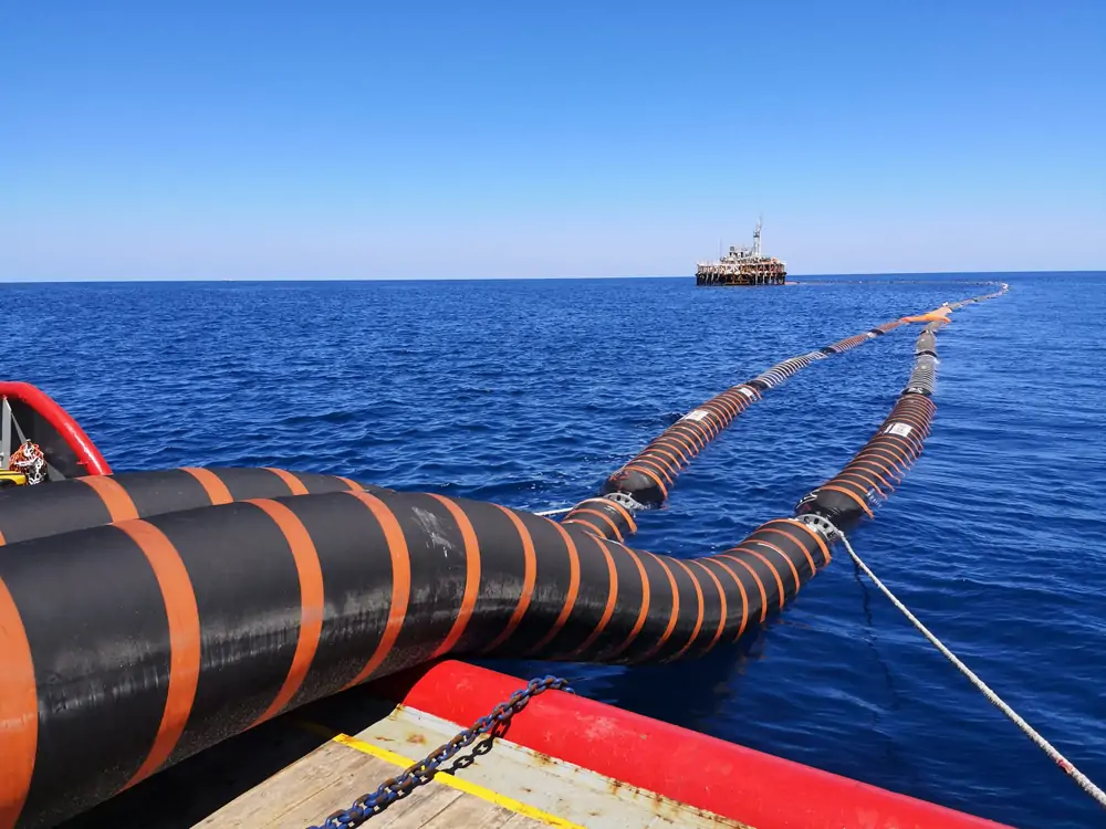
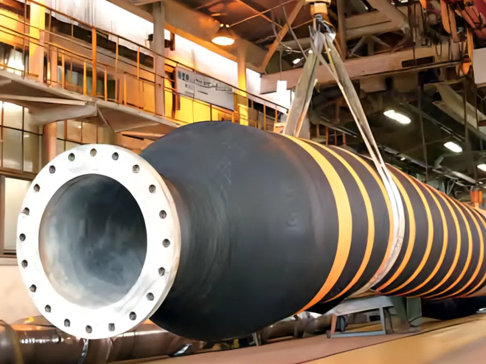
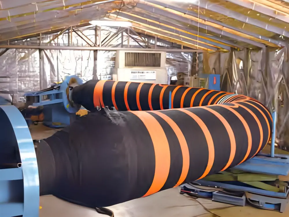
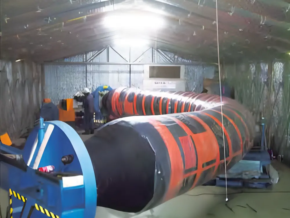
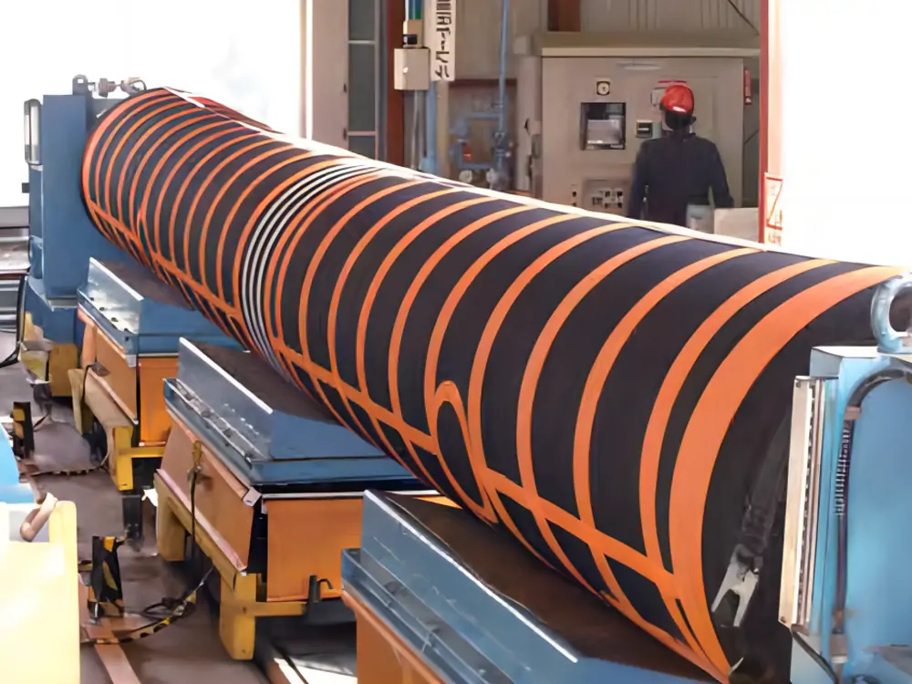
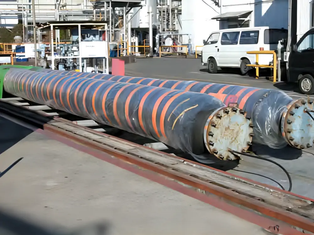
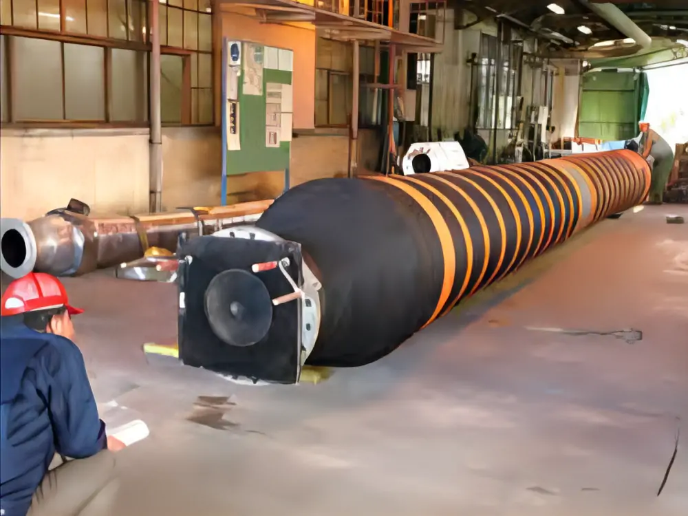
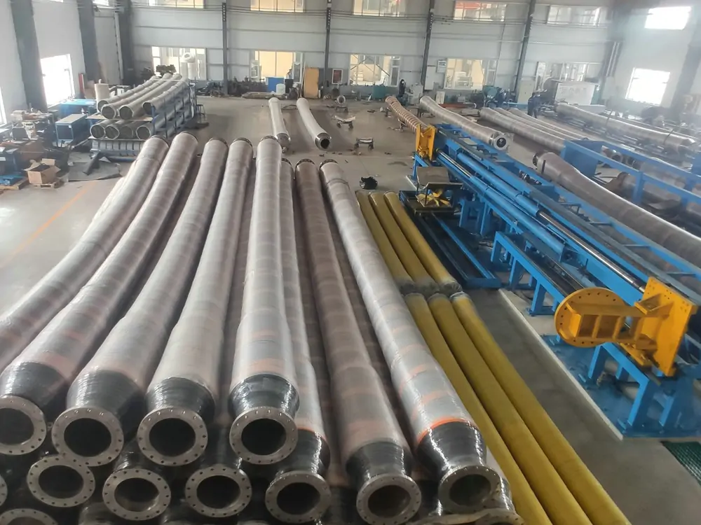
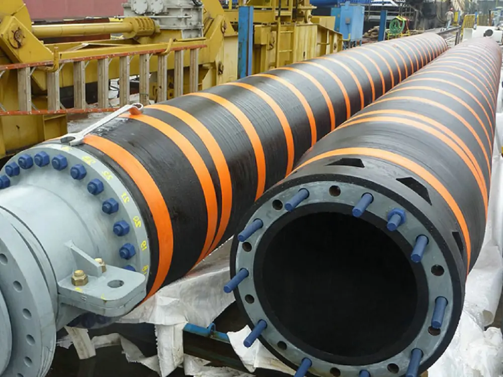
Mangueras de aceite flotantes Jerryborg
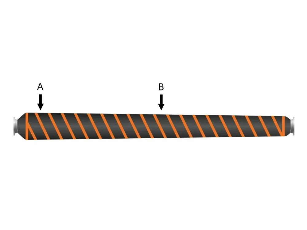
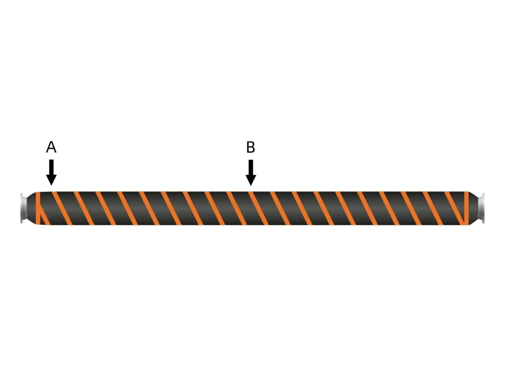
La manguera flotante para petróleo de Jerryborg Marine está diseñada para la descarga de petróleo en alta mar. Se trata de una manguera autoflotante que transfiere petróleo crudo y productos petrolíferos desde buques de alta mar y sistemas de amarre. La manguera flotante para petróleo es adecuada para la mayoría de los medios, como petróleo (hasta un 50% de contenido aromático), agua, salmuera, barita, cemento, etc.
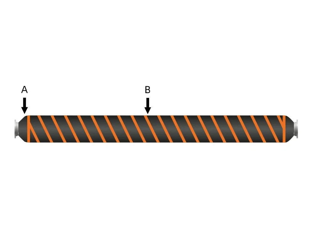
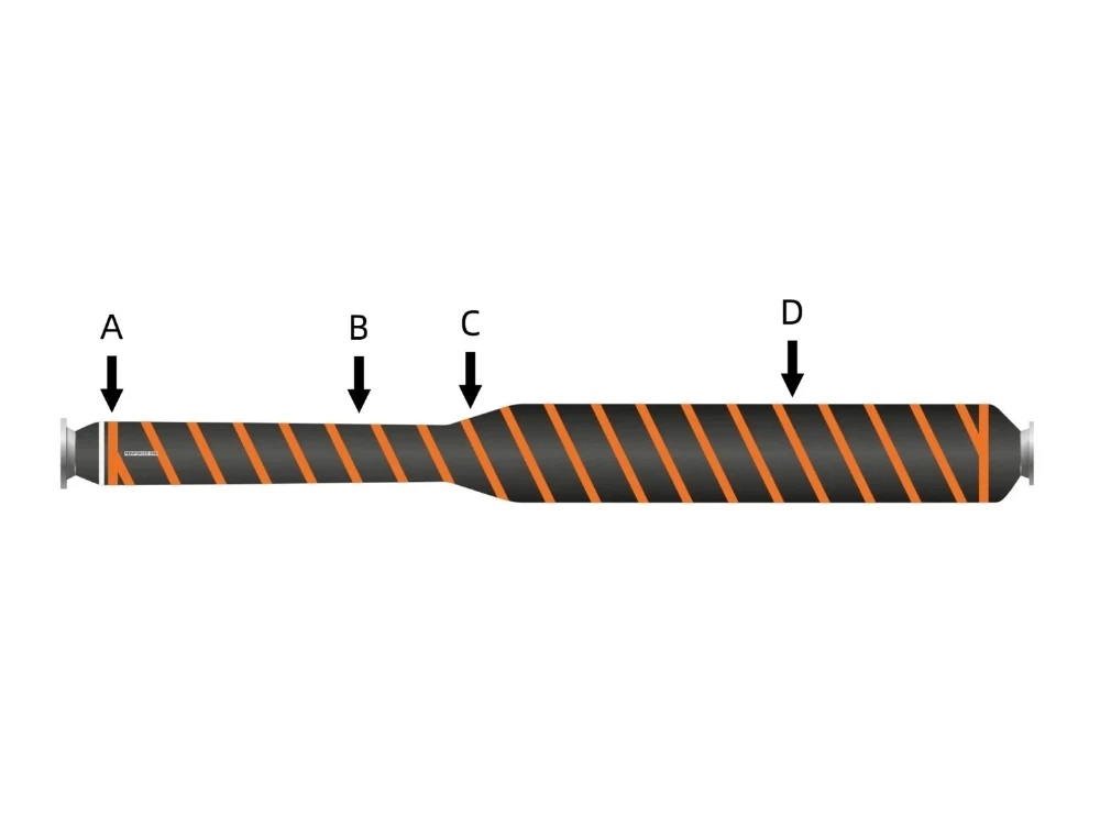
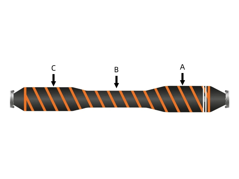
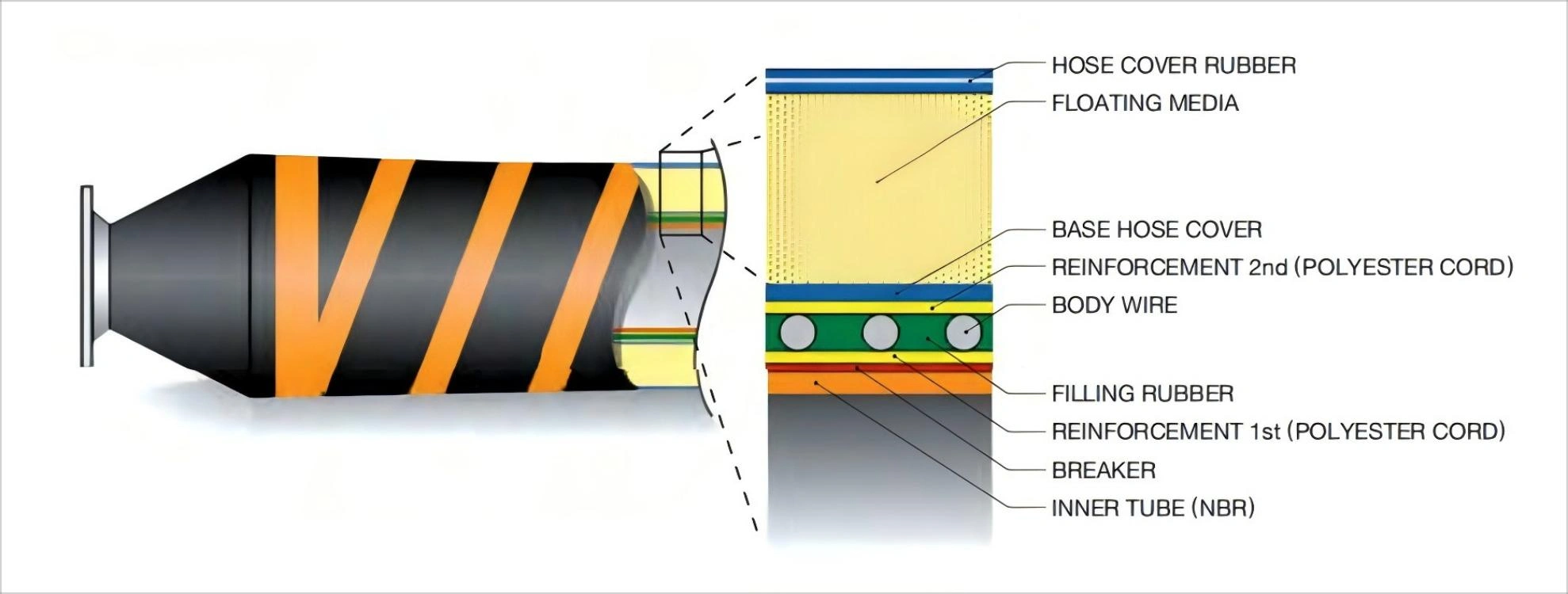
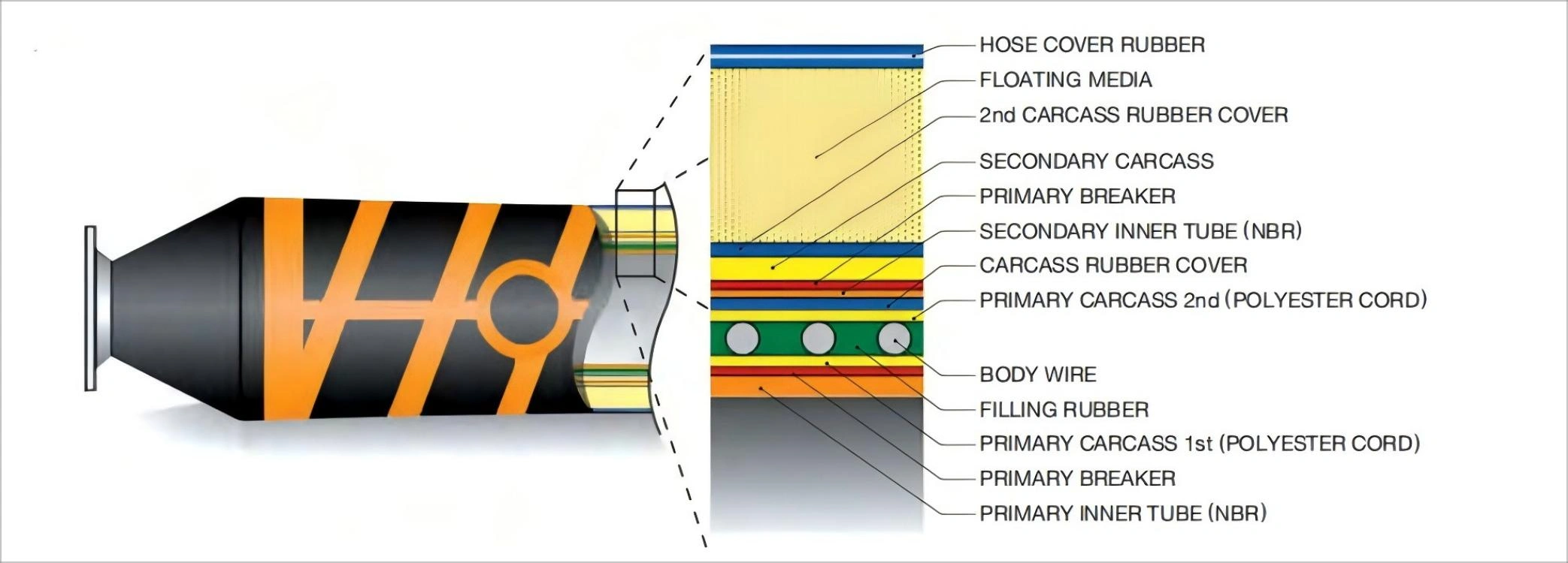
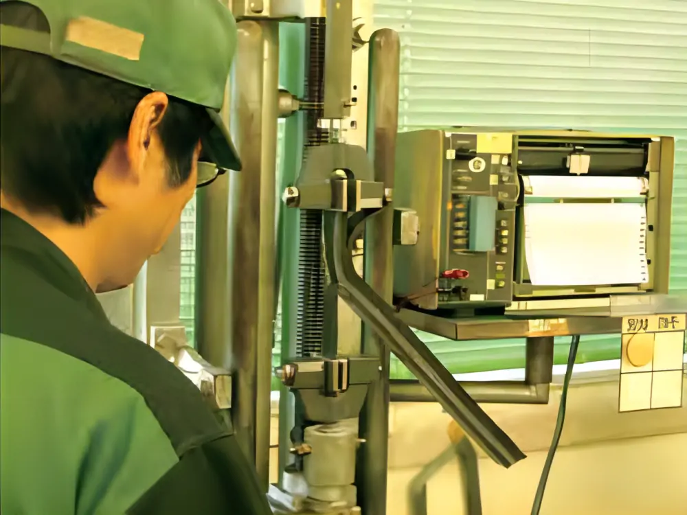
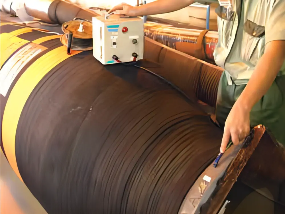
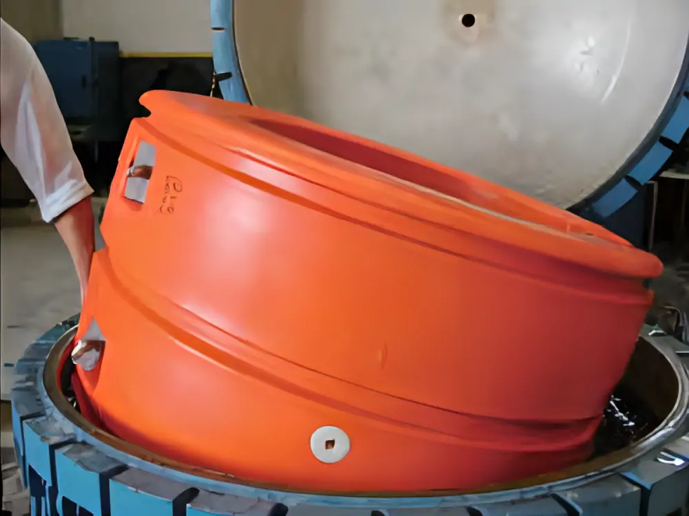
Las mangueras flotantes de aceite marino Jerryborg se diseñan y fabrican cumpliendo plenamente las normas OCIMF. Nuestras mangueras flotantes de aceite marinas se fabrican y prueban de acuerdo con los requisitos de las normas de calidad ISO 9001:2015.