Petrol su yüzeyine döküldükten sonra, kendi yerçekimi, rüzgar, akıntı ve diğer faktörlerin etkisi altında hızla yayılacak ve sürüklenecektir. Bu nedenle, petrol döküntüsüne acil müdahalenin birincil görevi, su alanının kirlilik aralığını azaltmak ve kirlilik hasarının derecesini hafifletmek için petrol döküntüsünü kontrol etmek ve daha fazla yayılmasını ve sürüklenmesini önlemek için mümkün olan en kısa sürede etkili önlemler almaktır. Petrol döküntüsünü daha küçük bir alanda kontrol altına almak ve daha fazla yayılmasını ve sürüklenmesini önlemek için alınan önlemlere petrol döküntüsünün kontrol altına alınması denir.
Bir petrol döküntüsü kazası durumunda, fiili duruma göre uygun çevreleme önlemleri ve çevreleme ekipmanı ve malzemeleri benimsenmelidir. Petrol döküntüsü muhafazası için kullanılabilecek ekipman ve malzemeler arasında doğal kaynaklar ve endüstriyel olarak üretilmiş ürünler bulunmaktadır. Doğal kaynaklar arasında mısır sapları, saman ve kütükler vb. yer alırken; endüstriyel olarak üretilen ürünler arasında petrol tutucu bomlar, halatlar ve ağlar vb. yer almaktadır. Bu bölümde esas olarak petrol tutucu bomlar tanıtılmaktadır.
Şu anda piyasada oldukça çeşitli tiplerde petrol tutma bomları bulunmaktadır. Çin Halk Cumhuriyeti'nin taşımacılık endüstrisi standardı - Petrol Muhafaza Bomu (JT/T2022-2001, bundan böyle “Petrol Muhafaza Bomu Standardı” olarak anılacaktır) petrol muhafaza bomlarını şu şekilde sınıflandırmaktadır:
1. Katı yüzdürme bomu
2. Çit bomu
3. Dış gergi bomu
4. Şişirilebilir bom
5. Kıyı mühür bomu
6. Yangına dayanıklı bom
IMO “Petrol Döküntüsü Acil Durum Eğitimi Model Metni ”nde petrol bomları perde tipi petrol bomları, çit tipi petrol bomları ve plaj tipi petrol bomları olmak üzere üç tipte sınıflandırılmıştır. Bu bölümde, IMO “Petrol Döküntüsü Acil Durum Eğitimi Model Metni ”ndeki sınıflandırmaya uygun olarak petrol bariyerleri tanıtılmaktadır.
Farklı petrol bomu türlerinin yapıları ve kullanımları aynı değildir. Gerçek duruma göre, uygun petrol bomunun seçilmesi ve makul konuşlandırma biçimlerinin benimsenmesi, petrol bomunun işlevlerini gerçekten yerine getirebilir ve petrol sızıntısının kontrol altına alınması ve geri kazanılması amacına ulaşabilir.
Bölüm 1: Yağ bariyerinin işlevi ve yapısal özellikleri.
1. Petrol patlamasının işlevleri
Petrol bariyerlerinin işlevleri üç ana başlık altında özetlenebilir: çevreleme ve yoğunlaştırma, petrol sızıntısının yönünü değiştirme ve olası petrol sızıntılarını önleme.
1.1 Petrol sızıntılarının tutulması ve yoğunlaştırılması
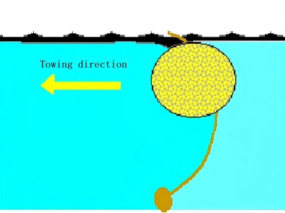
Bir petrol döküntüsü kazası meydana geldikten sonra, petrol döküntüsü güç akışı, rüzgar ve diğer dış faktörlerin etkisi altında hızla yayılacak ve sürüklenerek geniş bir kirlenmiş alan oluşturacaktır. Açık sularda, kıyıya yakın sularda veya limanlarda bir petrol döküntüsü meydana geldiğinde, petrol bariyerlerinin zamanında kurulması yayılan petrol döküntüsünü derhal kontrol edebilir. Petrol bariyerlerini sürükleyerek veya çevresindeki alanı azaltarak, petrol filmi geri kazanım için daha küçük bir alanda toplanabilir. Bu sadece petrol döküntüsünün yayılmasını engellemekle kalmaz, aynı zamanda petrol filminin kalınlığını artırarak Şekil 3-1'de gösterildiği gibi geri kazanımı veya diğer işlemleri kolaylaştırır.
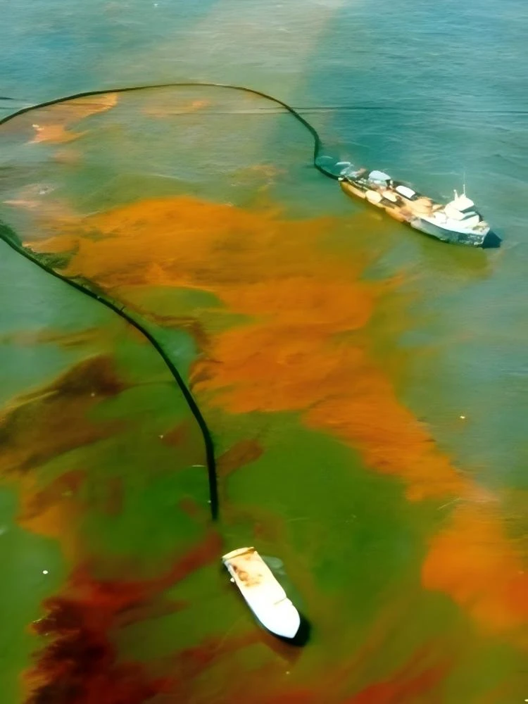
(3-1 Petrol döküntüsünün çevrelenmesi ve yoğunlaştırılması)
1.2 Petrol sızıntısı yönlendirme
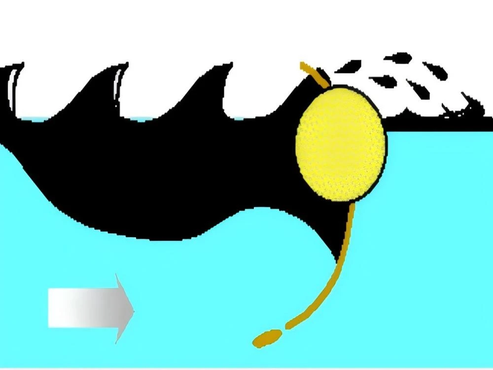
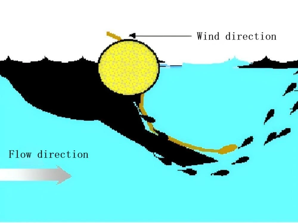
Bir petrol döküntüsü kazası meydana geldikten sonra, dış faktörlerin etkisi altında, dökülen petrol sürüklenecek ve istediği gibi yayılacaktır. Kurtarma operasyonunu kolaylaştırmak veya dökülen petrolü belirlenen yere yönlendirmek için, özellikle nehirlerde veya kıyıya yakın hızlı akıntı olan bölgelerde, kolay kurtarma için dökülen petrolün akış yönünü etkili bir şekilde kontrol etmek veya dökülen petrolün hassas alanlara girmesini önlemek için, genellikle önleme amacıyla belirli bir Açıda petrol bariyerleri kurulur. Petrol döküntüsünün yönünün değiştirilmesi için genellikle iki durum söz konusudur. Bir yaklaşım, tipik olarak su giriş noktalarına ve enerji santrallerine vb. yerleştirmek için uzun vadeli petrol bariyerleri kullanmaktır. Diğer bir durum ise geçici olarak petrol bariyerleri kurmaktır. Bu esas olarak bir petrol sızıntısı meydana geldiğinde uygulanır. Özel koşullara göre, petrol bariyerleri, dökülen petrolün yönünün değiştirilmesini sağlamak ve Şekil 3-2'de gösterildiği gibi geri kazanılması kolay alanlara veya diğer hassas olmayan kaynak alanlarına yönlendirmek için geçici olarak kurulur.
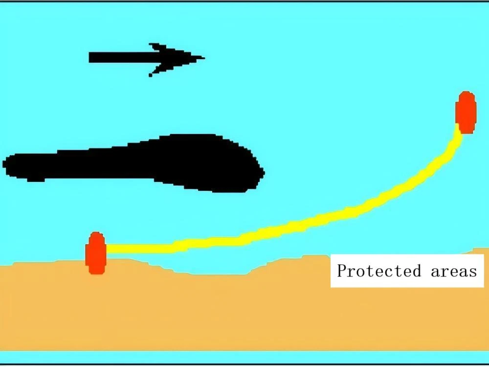
(3-2 Petrol sızıntısı yönlendirme)
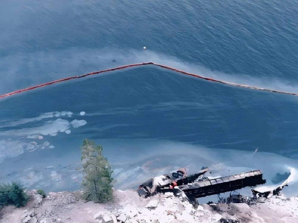
(3-3 Karaya oturan gemilerden kaynaklanabilecek olası petrol sızıntılarının önlenmesi)
1.3 Olası petrol sızıntılarını önleyin
Potansiyel petrol sızıntılarının önlenmesi genellikle petrol sızıntılarının önlenmesi ve kontrolü için yerel su koşullarına bağlı olarak petrol sızıntılarının meydana gelebileceği veya petrol sızıntısı riskinin bulunduğu alanlarda önceden petrol bariyerlerinin kurulması anlamına gelir. Bu şekilde bir petrol döküntüsü gerçekten meydana geldiğinde, petrol döküntüsünün yayılması önlenebilir, böylece petrol döküntüsünü muhafaza altına almak için zamanında kurtarma önlemleri alınabilir. Gemiler iskelede petrol yükleme ve boşaltma ya da demir yerinde petrol aktarma işlemleri gerçekleştirirken, genellikle kontrol için öngörülen gerekliliklere uygun olarak önceden petrol bariyerleri kurmaları gerekir. Bazen, karaya oturmuş veya batık gemiler için, Şekil 3-3'te gösterildiği gibi, kurtarılmadan önce fiili duruma göre uygun çevreleme de yapılmalıdır.
2. Yağ bariyerinin yapısı ve performans göstergeleri
Şu anda dünyada birçok petrol bomu üreticisi bulunmaktadır ve ayrıca birçok petrol bomu türü ve şekli vardır. Buna rağmen, petrol bomlarının temel yapısı büyük ölçüde benzerdir ve temel olarak yüzer bir gövde, bir etek gövdesi, gergi bantları, karşı ağırlıklar ve bağlantılardan oluşur.
- Yüzen gövde: Petrol bariyeri için kaldırma kuvveti sağlayan kısım. İşlevi, petrol bariyerine yüzdürme kuvveti sağlamak için hava veya yüzdürme malzemeleri kullanmak ve su yüzeyinde yüzmesini sağlamaktır. Yüzen gövde, petrol bariyerinin yüzey tabakasının içine veya yüzey tabakasının dışına yerleştirilebilir.
- Etek gövdesi: Yüzen gövdenin altındaki yağ bariyerinin sürekli kısmını ifade eder. İşlevi, yağ bariyerinin altından yağ kaçışını önlemek veya azaltmaktır.
- Gergi bandı: Petrol bariyerine uygulanan yatay çekme kuvvetine dayanabilen uzun bir bant bileşenini (zincir, kayış) ifade eder. Esas olarak rüzgar, dalgalar, gelgit akıntıları ve sürükleme tarafından üretilen çekme kuvvetine dayanmak için kullanılır.
- Karşı ağırlık: Yağ bariyerinin sarkmasını sağlayan ve performansını artıran bir balasttır. Yağ bariyerini su içinde ideal durumda tutabilir. Genellikle çelik veya kurşun malzemelerden yapılır veya balast olarak su kullanılır.
- Ortak: Yağ bariyerine kalıcı olarak takılan ve yağ bariyerinin her bir bölümünü veya diğer yardımcı tesisleri bağlamak için kullanılan bir cihaz.
Petrol bariyerinin performans göstergeleri genellikle fribord, su çekimi, yükseklik, toplam yükseklik, ağırlık, toplam kaldırma kuvveti, kaldırma kuvveti oranı ve petrol bariyerinin gerilme mukavemetini ifade eder.
- Freeboard: Yağ bariyerinin su hattı üzerindeki minimum dikey yüksekliği. Yağ bariyerinin üstünden yağ sıçramasını önlemek veya azaltmak için kullanılır.
Taslak: Yağ muhafazasının su hattının altındaki yüzey tabakasının minimum dikey derinliği. - Yükseklik: Serbest tahta ve yağ bariyerinin çekiminin toplamı.
Toplam yükseklik: Yağ bariyerinin maksimum dikey yüksekliği. - Ağırlık: Yağ bariyerinin mafsalı da dahil olmak üzere, yağ bariyerinin tamamen monte edilmiş bir bölümünün toplam ağırlığı.
- Toplam kaldırma kuvveti: Petrol bariyeri tamamen suya batırıldığında yer değiştiren tatlı suyun ağırlığı.
- Toplam kaldırma kuvveti oranı: Toplam kaldırma kuvvetinin petrol bariyerinin toplam ağırlığına oranı, genellikle kaldırma kuvveti oranı olarak adlandırılır. Yüksek bir kaldırma kuvveti oranı, petrol bariyerinin su altında kaldıktan sonra yüzer duruma dönme konusunda güçlü bir yeteneğe sahip olduğunu gösterir. Petrol bariyerinin bu kendini toparlama kabiliyetine dalga takip özelliği denir. Kaldırma kuvveti oranı ne kadar yüksekse, kendini toparlama kabiliyeti o kadar güçlü ve dalga takip performansı o kadar iyi olur.
- Çekme mukavemeti: Yağ bariyerinin gerilim altında kırıldığı kırılma kuvveti.
3. Yağ Bariyerinin Temel Bileşenleri ve Özellikleri
3.1 Perde tipi yağ bariyeri
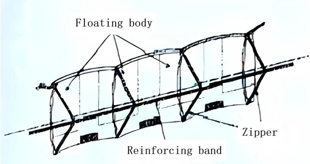
Perde tipi petrol bomunun temel bileşenleri Şekil 3-4'te gösterildiği gibi şamandıra, etek, gerdirme cihazı, balast ve mafsal vb. içerir. Şamandıra malzemesinin türüne göre, perde tipi yağ bomları şişirilebilir yağ bomları ve katı şamandıralı yağ bomları olarak ikiye ayrılabilir.
(3-4 Perde tipi yağ bariyerinin temel yapı şeması)
(3-5 Basınçla şişirilebilir yağ bariyerinin yapısı)
(1) Şişirilebilir yüzer gövdeli perde tipi petrol bariyerine şişirilebilir petrol bariyeri denir. Şişirme yöntemine göre, şişirilebilir petrol bariyerleri basınçla şişirilebilir olanlar (bkz. Şekil 3-5) ve kendiliğinden şişirilebilir olanlar (bkz. Şekil 3-6) olarak sınıflandırılabilir. Hava odasının yapısına göre, şişirilebilir yakıt bariyerleri tek hava odalı yakıt bariyerleri ve çok hava odalı (her bir hava odasının uzunluğu yaklaşık 2 ila 4 metredir) yakıt bariyerleri olarak sınıflandırılabilir. Şu anda, yurt içinde üretilen şişirilebilir akaryakıt bomları genellikle çok odacıklıdır. Fiili duruma bakıldığında, çoklu hava odacıklı petrol bariyeri daha iyi bir yüzdürme kabiliyetine sahiptir. Hava odalarından biri hasar görse bile, tüm petrol bariyeri sonuç olarak batmaz ve bu nedenle daha yaygın olarak kullanılır.
(3-6 Kendiliğinden Şişen Petrolle Mücadele Ağının Yapısı)
(3-7 Petrol Bomlarının Karşı Ağırlıkları)
(2) Silindirik veya granül köpük ile doldurulmuş veya çelik malzemelerden yapılmış perde tipi yağ bariyerine katı şamandıra tipi yağ bariyeri denir. Bunlar arasında, çelik ısıya dayanıklı malzemelerden yapılmış yüzer gövdeli yağ bariyerine yanmaz yağ bariyeri de denir.
Perde tipi yağ bariyerinin eteği esnektir ve nispeten bağımsız hareket edebilir.
Perde tipi yağ bariyerinin gergi bandı genellikle etek gövdesinin alt kenarında bulunan çelik zincirlerden veya çelik tel halatlardan oluşur. Bu gergi bandı aynı zamanda bir karşı ağırlık görevi de görür. Bazı perde tipi petrol bariyerlerinin gergi bantları, alt etek gövdesinin yerini almak üzere yüzer gövdenin altına yerleştirilmiştir. Bazı perde tipi petrol bariyerlerinde gergi kayışları yerine takviye kayışları kullanılır. Örneğin, bir PVC yağ bariyerinin ortasındaki takviye kayışı gergi kayışı olarak işlev görür.
Perde tipi petrol bomunun karşı ağırlık kısmı petrol bomunun eteğinin altına takılır. Karşı ağırlık genellikle çelik zincirler veya dökme demir bloklardan oluşur (bkz. Şekil 3-7). Bazı petrol bomlarında karşı ağırlık eteğin içinde veya doğrudan eteğin altına asılı olarak da bulunur.
Yapı bakımından, perde tipi petrol bomu aşağıdaki özelliklere sahiptir: İlk olarak, tipik olarak 5:1 ila 20:1 arasında değişen yüksek bir kaldırma kuvveti/ağırlık oranına sahiptir ve iyi bir dalga takip performansına sahiptir. Su çekimi bom yüksekliğinin beşte üçü kadardır ve perde tipi petrol bomunun fribord yüksekliği genellikle yüksekliğinin beşte ikisi kadardır. İkinci olarak, şişirilebilir perde tipi petrol bomu yavaş bir açılma hızına sahiptir, ancak söndürüldüğünde daha az yer kaplar ve temizlenmesi kolay pürüzsüz bir yüzeye sahiptir. Uzun bölmeli şişirilebilir perde tipi petrol bomunun şişirilmesi kolay ve hızlıdır, ancak delinmelere ve kesilmelere karşı hassastır ve zayıf dalga takip performansına sahiptir. Üçüncü olarak, uygulama yerleri açısından, büyük şişirilebilir perde tipi petrol bomları açık sular için uygunken, küçük olanlar kıyıya yakın, limanlar ve daha düşük akış hızlarına sahip diğer korunaklı sular için uygundur. Dördüncü olarak, şişirilebilir petrol bomları ile karşılaştırıldığında, katı şamandıra tipi petrol bomları hızlı bir yerleştirme hızına sahiptir ve delinmelere karşı hassas değildir, ancak kurtarılması karmaşıktır, daha fazla iş gücü gerektirir ve daha fazla yer kaplar.
3.2 Çit Tipi Petrol Bomu
Çit tipi petrol bomu (bkz. Şekil 3-8) yüzdürme gövdeleri, etek gövdeleri, gergi kayışları ve balast ağırlıkları vb. unsurlardan oluşur.
Izgara tipi yağ bariyerinin yüzen gövdesi genellikle katıdır ve ızgara şeklinde düzenlenmiştir. Etek malzemesi çoğunlukla cam elyaf ağdan veya diğer sert malzemelerden yapılır. Yüzer gövdeler arasındaki bağlantı esnek bölmeler kullanır ve bu da yağ bariyerinin yüzer hareketini daha esnek hale getirir. Izgara tipi yağ bariyerinin gergi bantları genellikle kayışlardan veya çelik tellerden yapılır ve yağ bariyerinin iç katmanına yerleştirilir. Karşı ağırlıklar genellikle çelik tel halatlardan, çelik zincirlerden ve dökme demir bloklardan vb. yapılır.
Yüzer gövdenin yerleşim şekline ve gergi bantları gibi yapısal özelliklere göre, insanlar ızgara tipi petrol bariyerini üç tipe ayırmaktadır: merkezi yüzer tip, harici yüzer tip ve harici takviye bandı tipi.
1) Merkezi yüzer tip çit yağ bariyeri bir grup merkezi yüzer gövdeye sahiptir, yani yüzer gövdeler yağ bariyerinin merkez hattının her iki tarafındadır ve simetriktir. Yüzen gövde grubu genellikle katı köpük disklerden oluşur ve bu yüzdürme diski yağ bariyerinin depolama hacmini nispeten azaltır.
2) Dış yüzer çit yağ bariyeri. Bu tip yağ bariyerinin yüzer gövdesi genellikle yağ bariyerinin bir tarafına yerleştirilir ve ayrıca yağ bariyerinin her iki tarafına da yerleştirilebilir.
3) Install an external reinforced belt fence to enclose the oil barrier. This kind of oil barrier also comes in two types. One is to configure the reinforcing band on the side facing the power flow direction (see Figure 3-9); Another approach is to configure the reinforcing belts on both sides and fix them to the top and bottom of the oil barrier with steel wire ropes.
(3-9 External reinforced belt fence enclosing the oil barrier)
(3-8 Fence-type oil enclosure structure)
The characteristics of the fence-type oil enclosure are: low buoyancy ratio, generally ranging from 3:1 to 6:1, poor wave-following performance, and generally not suitable for open sea areas. The free board of the oil barrier accounts for one-third of the total height of the oil barrier, and the draft accounts for two-thirds of the total height.
It has good anti-tidal performance and is suitable for long-term deployment in relatively closed water areas and rivers. The central floating type fence has a small contact area with water, poor swinging performance and is prone to rolling. The external floating type fence oil barrier has a large contact area with water, which enhances the anti-rolling performance, but the strength of the external floating body in water is relatively weak. The external reinforced belt type oil barrier has good anti-tidal performance, but its layout is complex and the reinforcing belt is prone to entanglement during recycling. The single-sided reinforced grid-type oil barrier can only be used in unidirectional tidal current waters. Overall, this kind of oil barrier is easy to manufacture and has a relatively low cost, but it has a large storage volume. The covering materials for the oil barrier mainly include rubber, PVC and polyurethane, etc.
From the current actual usage perspective, the curtain-type and fence-type oil barriers are the most commonly used types of oil barriers. Some manufacturers of oil barriers, based on the respective characteristics of the curtain-type and fence-type oil barriers, produce oil barriers that fall between the two. Therefore, it is sometimes very difficult to strictly distinguish between the curtain-type and fence-type oil barriers.
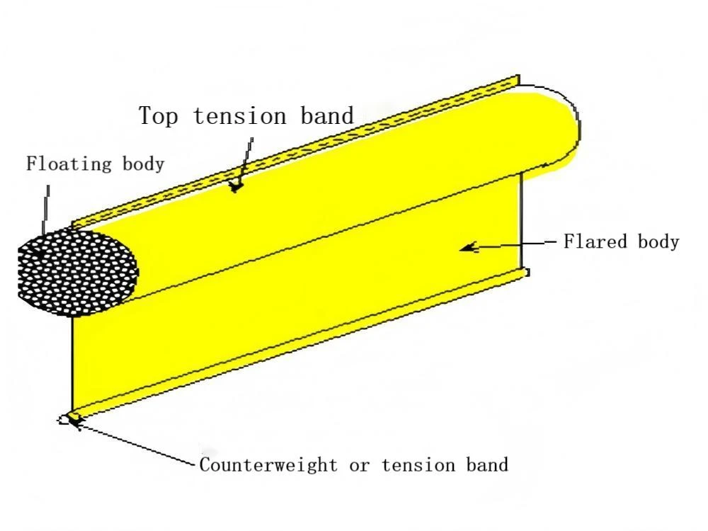
3.3 Kıyı tipi petrol bomları
When the oil spill spreads to the beach, it is difficult for ordinary oil booms to enclose the oil spill. Because when the water depth is less than the draft of the oil barrier, the oil barrier is very likely to tip over. In areas with high and low tides, the oil barriers are also difficult to adhere to the ground. At this point, the shore-type oil barrier should be used, and its structure is shown in Figure 3-10.
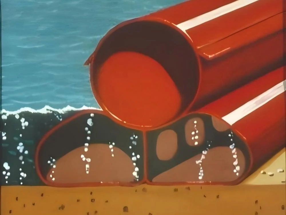
(3-10 Beach type oil enclosure structure)
The beach oil barrier is generally composed of three independent pipe cavities, each 10 to 25 meters long, forming a single unit. One of the pipe cavities is located at the top, while the other two are at the bottom, thus creating a “pin” shaped structure. The upper pipe cavity is filled with air and the two lower pipe cavities are filled with water to provide sufficient weight to keep the oil barrier in a sealed state with the ground or the beach.
The top tube cavity filled with air is the floating body of this kind of oil barrier, while the two tube cavities filled with water below are the skirt bodies of this kind of oil barrier. The draft is the vertical height of the two bottom pipe cavities after they are filled with water. The tension band is the structural material of the oil barrier itself. The counterweight is the water filled in the two bottom pipe cavities. At present, shore-type oil booms are mostly made of polyurethane materials.
As mentioned above, the shoreline type oil barrier is rather unique in design. The stemboard of this type of oil barrier is the height of a gas-filled tube cavity, and the draft accounts for approximately half of the total height of the oil barrier. The buoyancy ratio is usually 5:1 to 10:1. This type of oil barrier is very suitable for placement in the intertidal zone or at the junction of land and water to intercept oil spills. When using this type of oil barrier, generally, the placement location is selected first. Then, water and air are injected into the bottom pipe cavity and the top pipe cavity respectively. The amount of water injected should be appropriate; excessive water will affect the sealing effect with the ground.
From the structure of the shore-type oil barrier, the following main features can be summarized: Its application range is relatively narrow, generally only suitable for intercepting oil spills in the intertidal zone and at the junction of water and land. The ground where the oil barrier is placed should be relatively flat to achieve a relatively ideal sealing effect. On beaches with many rocks, the sealing effect will be affected. It can be connected and used in conjunction with other types of oil booms. Due to its unique structure, special care must be taken during deployment and recycling to prevent the surface from being punctured or scratched.
4. Yağ bariyeri konnektörü
The containment cage connector is a device used to connect each section of the containment cage to each other or to connect the containment cage to the quay wall, hull, etc. One function of the connector is to adjust the length of the oil barrier, and the other is to prevent the leakage of the floating oil between the oil barrier and the connected object. Different types and functions of oil barriers require different connectors for the oil barriers. When choosing a gas barrier, in addition to considering the various factors mentioned earlier, it is also necessary to focus on the connectors of the gas barrier itself, whether they meet the unified standards, and whether they can be connected and used with other gas barriers. This section introduces several common connectors.
4.1 Yağ bomları arasındaki konektörler
For ease of use, the oil barrier is usually equipped with a connector at certain intervals as needed, which is convenient for disassembly or connection. Considering factors such as the type and application area of the oil barrier, the connectors of the oil barrier vary greatly in terms of firmness and ease of disassembly, and there are many types. At present, there is no unified standard internationally. The United States requires the use of ASTM hook-type quick connectors, while China demands the use of three types of oil barrier connectors: hook-type, hinged type and rope-piercing type.
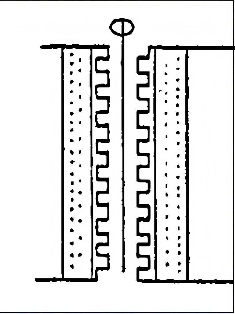
1) Hook type joint (see Figure 3-11) : Hook type joints have the advantages of convenient operation, easy connection and easy disassembly.
(3-11 Hook type joint structure)
(3-12 Hinge type joint)
2) Hinge-type joint (see Figure 3-12) : Hinge-type joints have high strength and reliable connection, making them more suitable for long-term installation of oil barriers.
3) Rope-piercing joint: The rope-piercing joint is a relatively primitive and outdated type of joint, often used in PVC solid float oil booms.
4.2 Yağ bariyeri ile rıhtım duvarı arasındaki bağlantılar
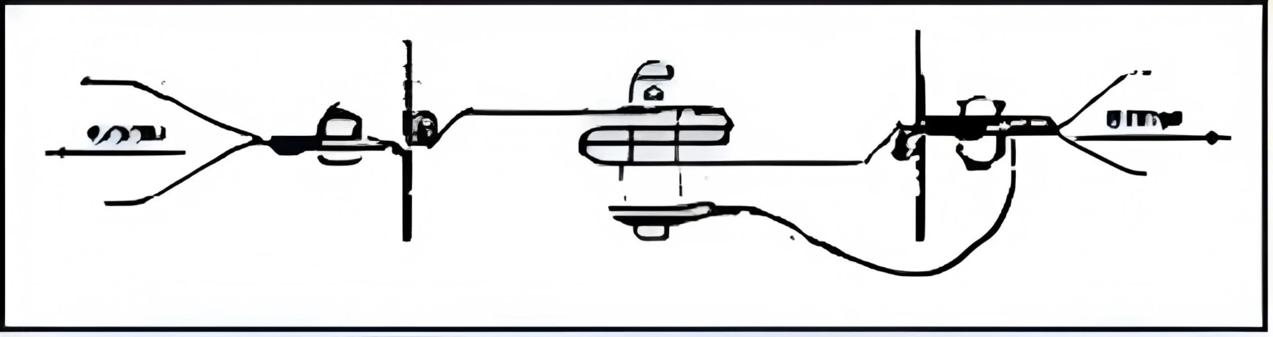
After setting up oil barriers at ports and docks, in order to prevent oil from overflowing and running away, it is necessary to ensure the relative sealing between the oil barriers and the mating sections or objects such as the hull. Due to the rise and fall of the tide and the inability of people to adjust the height of the oil barrier in time, oil spills often occur within the enclosure, resulting in the oil barrier being rendered ineffective. For this reason, through continuous practice, people have developed a kind of connector called tidal compensator (see Figure 3-13). It can automatically adjust the height of the oil barrier in a timely manner as the tide rises and falls without human intervention. It is a vertical sliding device. Its structure mainly consists of a cylindrical floating body, a vertical sliding groove and a hoop sleeve. When necessary, the entire device only needs to be fixed to the corresponding shore wall and connected to one end of the oil enclosure. This sliding connector is not only not affected by tidal fluctuations but also ensures the sealing between the oil barrier and the quay wall.
(3-13 Tidal Compensation Connector Structure)

(3-14 Magnetic connector)
4.3 Yağ bariyeri ile gövde arasındaki bağlantılar
This type of connector is a magnetic connector. The highly magnetic magnet is attached to the hull. The operator can manually adjust the actual height of the oil barrier according to the ship’s draft or tidal conditions to achieve the purpose of controlling oil overflow.
From this, it can be seen that in order to prevent oil spill and leakage, when using this type of connector, it is necessary to arrange for on-duty personnel to supervise regularly and adjust the height of the connector at any time according to the tide and the draft of the ship, etc.
Bölüm 2: Yağ Bariyerinin Uygulanması
1. Petrol Bariyerleri için Çevrenin Performans Gereklilikleri
In the “Standards for Oil-Containment Booms”, the waters where oil containment booms are used are classified into four types of water conditions: calm waters, calm and rapid-flowing waters, sheltered waters, and open waters. Calm waters refer to the waters where the wave height is between 0 and 0.3 meters and the water current speed is below 0.4 meters per second; calm and rapid-flowing waters refer to the waters where the wave height is between 0 and 0.3 meters and the water current speed is 0.4 meters per second or above; sheltered waters refer to the waters where the wave height is between 0 and 1 meter; open waters refer to the waters where the wave height is between 0 and 2 meters or 2 meters or above. Different water environments have different requirements for the performance of oil containment booms. No oil containment boom can be applicable to all kinds of water environments. Only by choosing an oil containment boom that meets the performance indicators according to the specific water environment can the functions and effects of the oil containment boom be fully exerted. Table 3-1 introduces the performance requirements of oil containment booms for different water environments in the IMO demonstration tutorial.
Form 3-1 Performance Requirements for Oil Barriers in Different water areas
| |
A calm lake bay with a wave height of less than 0.3 meters |
The water surface of a river with a current |
Nearshore waters of sheltered waters with a wave height of less than 1.5 meters |
Open waters with a wave height greater than 1.0 meter |
| Freeboard |
0.2-0.5m |
0.3-0.5m |
0.4-0.6m |
0.5-1.0m |
| Draught |
0.2-0.5m |
0.3-0.7m |
0.4-0.8m |
0.6-1.5m |
| Buoyancy to weight ratio |
3:1-10:1 |
3:1-10:1 |
5:1-12:1 |
8:1-15:1 |
| Total tension strength |
≥10Kn |
≥30Kn |
≥50Kn |
≥150Kn |
2. Petrol Bomlarının Seçimi için Genel İlkeler
When selecting oil booms, the performance requirements of the water environment for the oil booms and the basic performance parameters of the oil booms should be considered first, and then the on-site environment and the operational performance of the oil booms.
2.1 Water environment: The water environment generally refers to three situations; the first is a calm water surface with a wave height of 0.3m (such as lakes and ports, etc.); the second is a calm water surface with current (such as rivers); the third is sheltered waters with waves higher than 1.0m and open waters with waves higher than 1.0m.
2.2 Petrol tutma bomunun performans parametreleri: Burada, petrol tutma bomunun performans parametreleri fribord, draft, draft-ağırlık oranı ve toplam gerilme mukavemetini ifade eder.
2.3 Petrol tutma bomunun operasyonel performansı: Petrol tutma bomunun operasyonel performansı genellikle petrol tutma bomunun dayanıklılığını, kolay konuşlandırılmasını, iyi kaldırma kuvvetini, hızlı konuşlandırma hızını, iyi kıyı şeridi sızdırmazlık performansını, kolay bakım ve bakımı, uygun depolama ve uygulanabilirliği içerir.
Bir petrol tutma bomu seçerken, yukarıda belirtilen tüm faktörleri dikkatlice değerlendirmenin yanı sıra, tutma, saptırma, koruma veya dağıtım gereksinimleri, çalışma ortamı ve bakım ve kullanım gibi diğer faktörler gibi dağıtım amacına göre performans ve fiyat açısından bir karşılaştırma da yapılmalıdır. Böylece, fiili durum için en uygun petrol tutma bomu seçilebilir. Tablo 3-2“de ”Kuzey Denizi Bölgesi için Petrol Döküntüsü Acil Durum Planı "nda petrol tutma bomları için seçim kılavuzları listelenmektedir.
3. Petrolle Mücadele Bomlarının Seçimine İlişkin Örnekler:
3.1 Açık Su Alanlarında Petrol Taşkını Bariyerlerinin Seçimi
Açık sularda bir petrol tutma bomu seçerken, aşağıdaki faktörler esas olarak dikkate alınmalıdır: (1) Bomun gücü: Seçilen petrol tutma bomu rüzgar, dalgalar ve gelgitlerin boma getirdiği çeşitli dış kuvvetlere dayanabilecek kadar güçlü olmalıdır; (2) Yerleştirme kolaylığı: Seçilen petrol tutma bomu gemiden veya diğer yerlerden su yüzeyine rahatça yerleştirilebilmeli ve ideal bir tutma şekli oluşturabilmelidir; (3) Depolama alanı: Bir petrol döküntüsü meydana geldiğinde, döküntü bölgesine giden gemiler çok sayıda acil durum ekipmanı taşıyabilir. Bu durumda, geminin güvertesinde yeterli alan olup olmadığını göz önünde bulundurmak gerekir; (4) Kaldırma kuvveti/ağırlık oranı: Deneyimler, açık sularda konuşlandırılan petrol tutma bomunun kaldırma kuvveti/ağırlık oranının 8:1'in üzerinde olması gerektiğini göstermektedir; (5) Fribord ve su çekimi: Fribord ve draft boyutları geminin faaliyet gösterdiği su alanının dalga yüksekliği ve gelgit koşullarına göre belirlenmelidir.
Yukarıda bahsedilen tüm çeşitli faktörler göz önünde bulundurulduğunda ve Petrol Muhafaza Botlarının Seçimine İlişkin Kılavuzun Tablo 3-2'sine bakıldığında, açık sular için şişirilebilir perde tipi petrol muhafaza botlarının en ideal seçim olduğunu görmek zor değildir.
3.2 Nehirler ve Kıyıya Yakın Sular için Petrolle Mücadele Bomlarının Seçimi
Nehirlere ve kıyıya yakın sulara petrol bomları yerleştirilirken genel amaç petrol sızıntılarının yönünü değiştirmektir. Konuşlandırma alanları nispeten geniştir ve konuşlandırma süresi nispeten uzundur. Bu nedenle, petrol bomlarını seçerken dikkate alınması gereken ana faktörler şunlardır: (1) Delinmeye karşı direnç: Delinmeye karşı daha az hassas olan katı şamandıra tipi petrol bomlarının veya şişirilebilir kauçuk petrol bomlarının kullanılması tavsiye edilir; (2) Akıntı ve gelgitler: Zayıf akıntıların olduğu bölgelerde standart merkez tipi ızgara tipi yağ bomları kullanılabilir; akıntıların ve güçlü su akışının olduğu bölgelerde takviyeli kayışlara sahip ızgara tipi yağ bomları veya takviye kayışları olarak ağırlıklı zincirlere sahip perde tipi yağ bomları seçilebilir.
3.3 İskeleyi Çevreleyen Su Alanında Petrolle Mücadele Bomlarının Seçimi
Rıhtım sularının korunması amacıyla, ilk göz önünde bulundurulması gereken husus hızlı konuşlandırma kolaylığı olmalıdır. Kendiliğinden şişen yağ bomları veya katı köpük bariyerli yağ bomları bu amaç için uygundur. Eğer iskele alanındaki su akışı hızlı ise, bariyerli yağ bomları veya katı yüzer tip yağ bomları seçilmelidir. Sabit veya yarı sabit yağ bomları güçlü dalgaların olduğu bir rıhtımda konuşlandırılacaksa, yüksek mukavemetli ve yüksek yüzdürme-ağırlık oranına sahip yağ bomları seçilmelidir. Kauçuk yağ bomları veya katı köpük bariyerli yağ bomları bu durum için uygundur. Bu iki tip petrol bomu keskin nesnelere karşı daha az hassastır.
Form 3-2 Petrolle Mücadele Bomlarının Seçimi için Kılavuz İlkeler
| Sembol Açıklaması 1、İyi 2、Orta 3、Zayıf |
Yağ tutucu bom tipi |
|||||
| Katı şamandıra tipi |
Şişirilebilir tip |
Kendiliğinden şişen tip |
Gergi elemanı tipi |
Çit tip |
||
| Çevresel Koşullar |
Açık Deniz Hs>3ft V<1kn |
2 |
1 |
2 |
1 |
2 |
| Liman Hs>3ft V<1kn |
1 |
1 |
1 |
2 |
2 |
|
| Sakin su Hs>3ft V<.5kn |
1 |
1 |
1 |
2 |
1 |
|
| Yüksek hızlı akış V>1kn |
2 |
2 |
3 |
1 |
3 |
|
| Sığ su Su derinliği <1ft |
1 |
2 |
2 |
3 |
3 |
|
| Performans Karakteristiği |
Sert nesnelerin varlığında kullanım için |
1 |
2 |
3 |
3 |
2 |
| Aşırı kaldırma kuvveti |
2 |
1 |
1 |
2 |
3 |
|
| Stokastik Volatilite |
2 |
1 |
1 |
2 |
3 |
|
| Güç |
2 |
1 |
3 |
1 |
1 |
|
| Çalışma Karakteristikleri |
Hareketli |
2 |
2 |
1 |
3 |
2 |
| Kolay temizlenir |
1 |
1 |
1 |
3 |
1 |
|
| Sıkılabilirlik |
3 |
1 |
1 |
2 |
3 |
|
4. Petrol Muhafaza Botlarının Konuşlandırma Şekilleri
Petrol sızıntıları için petrol tutucu bomların tutma, yönlendirme ve önleme işlevleri uygun konuşlandırma biçimleriyle gerçekleştirilebilir. Farklı su alanlarına göre, petrol tutucu bomların yerleştirilme biçimleri temel olarak iki duruma ayrılabilir: açık sulardaki yerleştirme biçimleri ve kıyıya yakın alanlar ve nehirlerdeki yerleştirme biçimleri.
4.1 Açık sularda petrol bomlarının konuşlanma şekilleri
Açık sularda petrol bomları konuşlandırılırken, konuşlandırma şekli esas olarak konuşlandırmanın amacına ve konuşlandırma operasyonuna dahil olan gemi sayısına bağlıdır. Tipik konuşlandırma biçimleri arasında tek gemili konuşlandırma (tek taraflı çekme ve çift taraflı çekme), iki gemili konuşlandırma ve üç gemili konuşlandırma yer alır.
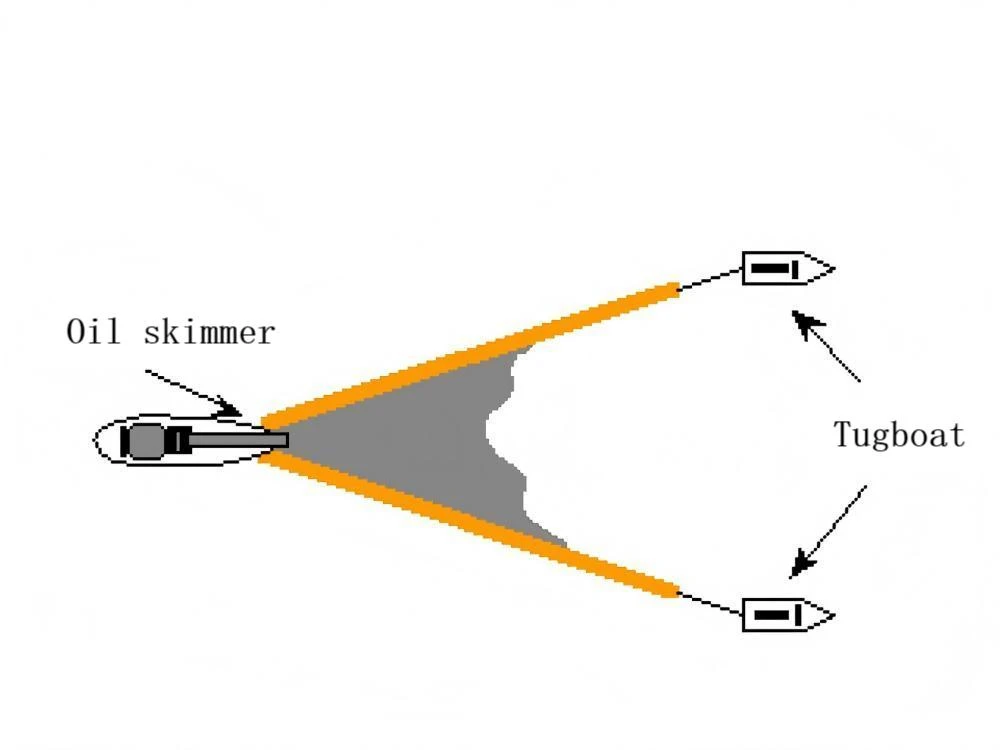
(1) Tek gemilik konuşlandırma formu
Tek gemili konuşlandırma şekli, petrol döküntüsü kurtarma gemileri, uzatılabilir çubuklar (uzatılabilir kollar ve şamandıralar), petrol tutma bomları veya sıyırıcılarla donatılmış petrol tutma bomları gibi ekipmanlar gerektirir. Uzatılabilir çubukların uzunluğu geminin büyüklüğüne göre seçilir ve genellikle 5-15 metredir. Tek gemili yedekleme, yüzeydeki petrol sızıntısının kontrol altına alınması ve süpürülmesi için tek taraflı yedekleme (uzatılabilir çubukların geminin bir tarafından uzatılması) veya çift taraflı yedekleme (uzatılabilir çubukların geminin her iki tarafından uzatılması) ile gerçekleştirilebilir. Petrol tutma bomunu çeken tek geminin şekli genellikle Şekil 3-15'te gösterildiği gibi V şeklindedir. Ancak, büyük ölçekli petrol tutma bomlarını bu şekilde konuşlandırırken, geminin manevra kabiliyeti belirli bir ölçüde sınırlanacaktır.
Tek taraflı V-şekilli çekme, petrol tutma bomunun sırasıyla gemiye ve uzatılmış kolun tepesine bağlanmasını içerir. Bir taraftaki V şeklindeki bomun uzunluğu genellikle geminin boyutuna bağlı olarak 10 m ila 50 m arasındadır. Bu konuşlandırma biçimi yalnızca bir kurtarma alanı oluşturabilir, bu nedenle sıyırıcı, kurtarma için V şeklindeki bomun altına, yani petrol döküntüsünün en yoğun olduğu yere yerleştirilmelidir. Kurtarma işlemi sırasında, daha kolay kurtarma için V şeklindeki bomun altını geminin bordasına mümkün olduğunca yakın hale getirmek için bom kolunu sürekli olarak gözlemlemek ve ayarlamak gerekir. Tek taraflı çekme sırasında geri kazanılan petrol döküntüsü katı haldeyse, geri kazanım için bir toplama ağı kullanılmalıdır.
(3-15 Petrol bomlarının tek gemi ile tek taraflı çekilmesi)
(3-16 Bir petrol bomunu J şeklinde yerleştiren iki gemi)
Bir geminin her iki tarafına da petrol bomları yerleştirilirse, iki kurtarma alanı oluşturulabilir. Bu sadece geminin her iki tarafındaki kuvvetlerin temelde aynı olmasını sağlamakla kalmaz, aynı zamanda geminin bu durumda manevra yapmasını sadece bir tarafa bom yerleştirilmesine kıyasla daha kolay hale getirir. Her iki tarafa da bom yerleştirmenin geniş bir alan gerektirdiğini belirtmek gerekir. Çekilebilecek su alanı darsa, çift taraflı çekme benimsenemez.
Başarılı bir çift taraflı çekme operasyonu çok sayıda ilgili ekipman gerektirir. Bu nedenle, bir gemi için, yeterli petrol döküntüsü kurtarma ve depolama ekipmanını depolamak için geniş bir güverte alanının yanı sıra temizleme işlemleri için acil durum personelini barındıracak yeterli alan gerekir.
(2) İki geminin konuşlanma şekilleri
For deploying the oil containment boom by two vessels, the J-shaped deployment is usually adopted, also known as J-shaped towing (see Figure 3-16).
This deployment form generally requires two vessels. One serves as the main towing vessel, used to tow the shorter end of the oil containment boom and store the necessary recovery equipment and recovery personnel; the other serves as the towing vessel, used to tow the longer end of the oil containment boom. The length of the oil containment boom should be 200-400m. The length of the oil containment boom from the main towing vessel to the bottom of the J-shaped structure is 20-40m, and the skimming device is placed at the bottom of the J-shaped structure. The oil containment boom should be as close as possible to one side of the main towing vessel (10-20m) to facilitate the operation of the skimming device or other recovery equipment.
In order to obtain and maintain the ideal shape of the bottom of the oil containment boom, the shape of the bottom of the boom can be appropriately adjusted by pulling the rope connecting the boom with the ship.
When the two-ship deployment form is used for the oil spill diversion purpose, the length of the oil containment boom is generally 100 – 400 meters. If the boom is too long, it will be difficult for the auxiliary vessel to maintain the ideal position, and the efficiency of the system will decline.
When conducting the operation of towing two vessels, generally speaking, the main towing vessel serves as the commanding vessel. The main towing vessel should promptly and accurately issue instructions to the preceding towing vessel based on the situation of oil spill containment and sweeping. The towing vessels should maintain good communication with the main towing vessel at all times and adjust their course and speed in accordance with the instructions in a timely manner. Only in this way can a good J-shaped containment and sweeping form be maintained at all times, achieving the desired effect of oil recovery.
(3) Deployment Form of Three Vessels
In order to increase the coverage area of oil spill containment, people gradually discovered in practice that using three vessels for deploying and sweeping oil containment booms is more effective. The deployment form of three vessels usually adopts U-shaped (see Figure 3-17) or open U-shaped containment shapes. The U-shaped containment mainly uses two vessels to tow the oil containment boom in parallel. During towing, the length of the oil containment boom generally needs to be 600 meters. Compared with J-shaped towing, towing in parallel with two vessels is easier to maintain the correct position. While the first two towing vessels are advancing simultaneously, the third vessel should always be on the outside of the bottom of the U shape, based on the speed of the two towing vessels, and use other suitable recovery equipment such as skimmers to recover the spilled oil trapped at the bottom of the U shape. This form of containment and sweeping operation has a large recovery volume. Therefore, before the operation, it is necessary to fully consider the capacity of the third vessel (the recovery vessel) to avoid having to return halfway or repeatedly change the recovery vessels due to insufficient capacity, which brings inconvenience to continuous operation.
The open U-shaped containment structure is developed from the U-shaped containment structure. The two sections of oil containment booms extend 3-10m to both sides at the opening, forming a funnel. The bottom of the U-shaped structure is adjusted by ropes to make the opening width 5-10m, thereby reducing the impact of turbulence on the floating oil. This form can control the flow of spilled oil and make the recovery work easier. Then, through the third vessel, spill oil recovery is carried out using single-side or double-side containment sweeping.
(3-17 Three-ship U-shaped deployment of oil booms)
(3-18 Three vessels deploy the oil containment boom in an U-shaped pattern)
The three deployment forms mentioned above, no matter which one it is, as the main towing vessel or the vessel responsible for the recovery operation, when conducting the enclosed sweeping recovery operation, one should always pay attention to observing whether there are vortices or re-appearing oil films floating behind the oil containment boom. If such phenomena occur, it indicates that the towing speed is too fast. The vessel should gradually slow down until these phenomena disappear.
4.2 Petrol bomlarının kıyıya yakın sularda ve nehirlerde konuşlandırılma biçimleri
For the deployment of oil booms in nearshore waters, the form adopted often depends on the purpose of deployment. If the purpose is to contain oil spills, especially in areas such as intertidal zones where land and water alternate, it is best to use the form where the shore-based oil boom is connected with other booms and used in series, placing the end connected with the shore-based boom on the side closer to the shore. If it is for diversion, it should be deployed in a multi-layer overlapping form for stepwise diversion. In rivers, for the purposes of oil spill containment or diversion, the main deployment forms of oil booms include shoulder-mounted and staggered shoulder-mounted forms (see Figure 3-19).
(3-19 Shoulder badge style and interlaced shoulder badge style deployment forms)
The deployment methods of oil booms in nearshore areas and rivers are different from those in open waters. To ensure the effectiveness of the booms, the following factors should be mainly considered:
(1)Water Environment: The water environment referred to here mainly refers to the flow direction and velocity of the proposed protected water area, so as to determine the reasonable deployment angle. Experience shows that when the flow velocity relative to the vertical direction of the oil containment boom exceeds 0.7 knots, the spilled oil is likely to escape from under the oil containment boom and cannot achieve the purpose of oil containment. Therefore, when deploying the oil containment boom in rivers or coastal waters, attention should be paid to forming a certain angle between the deployment of the oil containment boom and the flow direction, and adjusting it in time according to the change of the flow direction to alleviate the drift speed of the spilled oil relative to the oil containment boom. The larger the flow velocity, the smaller the angle between the oil containment boom and the flow velocity should be. At the same time, attention should also be paid to the length of the oil containment boom. Depending on specific needs, the length of the oil containment boom should be increased or decreased. Generally, in the river area, for oil spill containment, the length of the oil containment boom is approximately twice the width of the river. Due to the rapid flow of the river, the phenomenon of spilled oil escape often occurs. In response to this situation, multiple oil containment booms can be overlappedly deployed to reduce the occurrence of spilled oil escape. Table 3-3 lists the deployment angles and lengths of the oil containment booms in rivers.
Form 3-3 The required angle and length for deploying oil containment booms in the river.
| Flow rate (knot) |
The angle (in degrees) between the oil containment boom and the shoreline |
The length of the oil boom relative to the width of the river |
| 0.7 |
90 |
1.0 times the width of the river |
| 1.0 |
45 |
1.4 times the width of the river |
| 1.5 |
30 |
2.0 times the width of the river |
| 2.0 |
20 |
3.0 times the width of the river |
| 2.5 |
16 |
3.5 times the width of the river |
| 3.0 |
15 |
4.3 times the width of the river |
| 3.5 |
11 |
5.0 times the width of the river |
| 4.0 |
10 |
5.7 times the width of the river |
| 5.0 |
8 |
7.0 times the width of the river |
For example: The flow rate is 1.5 knots, the deployment angle is 30 degrees, and the length of the oil containment boom should be twice the width of the river.
(2) Selection of the locations for deploying oil booms. Most rivers have relatively calm water areas, which are generally located on the inner side of river bends, in areas with vegetation, or where rocks protrude. These are the best locations for oil spill diversion and also ideal places for oil spill recovery (see Figure 3-20).
When implementing the containment operation, based on the navigation conditions, the oil containment boom can be divided into two parts for oil spill interception. Do not place the oil containment boom across the river to avoid hindering the entry and exit of vessels to and from the area. Moreover, in terms of the deployment form of the oil containment boom, under certain conditions, shorter oil containment booms are easier to be deployed and formed than longer ones. This point should be taken into consideration during the deployment operation. As long as the containment objective can be achieved, the length of the oil containment boom should be shortened as much as possible. This can also reduce the subsequent work of oil containment boom recovery and cleaning.
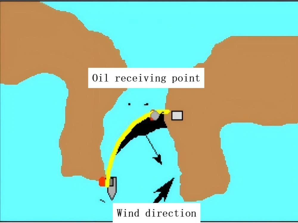
(3-20 Selection of Deployment Locations for Oil Spill Control)
During the operation of oil spill containment, it is often observed that while the oil containment boom is controlling the oil spill, a considerable amount of garbage, such as weeds, branches and leaves, will mix with the floating oil and float in together, gathering on the side of the containment boom. Generally, these garbage will not cause any damage to the containment boom, but they will have some impact on the skimmers used in the recovery operation. Therefore, the operation personnel should pay attention to observing and, as soon as possible, remove the garbage to ensure that the skimmers can continuously and efficiently carry out the oil spill recovery operation.
In order to prevent floating garbage from entering the oil booms, logs can be placed upstream of the booms to intercept the garbage in advance, thereby reducing the impact of floating garbage on the booms on the water surface. The logs used for intercepting garbage must be securely fastened to avoid being washed away by the water flow and causing unnecessary damage.
(3) Tidal range and water depth of the local waters: In the nearshore and shallow water areas, when deploying oil booms, it is necessary to consider whether the tidal range and water depth of the area can meet the draft requirements of the oil booms. Generally speaking, the water depth in the area where the oil booms are deployed should be at least three times the draft of the oil booms. Otherwise, if the water depth is insufficient, even if the oil booms are deployed, they will lose their containment effect. For shallow water areas or areas with insufficient water depth, it is best to consider using them in combination with shore-based oil booms according to the actual situation to prevent accidental oil spill from causing pollution to the riverbanks and intertidal zones.
5. Petrolle Mücadele Bomlarının Konuşlandırılması
Before deploying the oil-fighting booms, they should be assembled as completely as possible on the land or on the deck of the vessel according to the required approximate length. The required length can be referred to in Table 3-4 for the deployment length of oil-fighting booms under normal conditions. There are many methods for deploying oil-fighting booms depending on the type of booms and the usage area. They can be deployed from the shore, the wharf, the vessel, from the reel, from the container, or from the platform. The common methods are deployment from the vessel and deployment from the shore.
Form 3-4 The deployment length of the oil containment boom under normal conditions
| Application scenarios |
Water environment |
Length of the oil-boom |
| Blockade of the sunken vessel |
Depends on the sea conditions |
3X the length of the ship |
| Containment of leakage at the loading and unloading point |
Calm water area or depends on the sea conditions |
1.5X the length of the ship |
| Used in conjunction with an oil skimmer |
On the sea |
460 – 610 meters of each skimming device |
| Protect the river estuary |
Calm water area |
3-4 times the width of the water area |
| Protected bays, harbors, marshes |
Calm water area or depends on the sea conditions |
(1.5 times+flow rate) of width of the water area |
5.1 Gemiden konuşlandırma
When deploying the oil booms from a ship, they should be stored and fixed on the ship’s deck. The following steps should be followed when deploying the oil booms from a ship:
(1) Selection of towing vessels. When deploying oil containment booms, choosing the right towing vessels is also crucial for achieving effective containment. When selecting towing vessels, one must consider the towing capacity of the vessels. Generally, it can be calculated that for every 200 (Newton) of towing force, it is equivalent to 1 horsepower of the engine inside the vessel. For example, if a single vessel towing is responsible for containing an oil spill boom with a resistance of 20,000 (Newton), a vessel with a towing capacity of more than 100 horsepower must be selected. If a U-shaped towing with a resistance of 40,000 (Newton) is carried out using two vessels, two vessels with a towing capacity of more than 1,000 horsepower each must be selected. In addition to considering the towing capacity, when the towing vessel is also responsible for oil spill recovery (single vessel deployment), the deck space must also be considered, whether it is sufficient to load the necessary cleaning and pollution control equipment, and whether there is sufficient cargo space.
(2) Determination of Deployment Scheme. The success of rapid deployment of oil containment booms and their effectiveness in controlling oil spills is highly dependent on the determination of the deployment scheme. Main considerations should include the type of containment booms to be used, their length, the deployment platform, and the deployment methods. Taking vessel deployment as an example, the scale of the oil spill and the surrounding water environment should be taken into account to determine the size of the main and auxiliary tugboats and their supporting auxiliary equipment. At the same time, the number of personnel involved in the containment operation on board the vessel should be determined, and their responsibilities should be clearly defined. Specific operation steps and communication methods should be clarified, and the towing route should be preliminarily drawn up to ensure that each participant is well-informed and that the actions are unified and in step. After the deployment scheme is determined, all vessels and personnel involved in the containment operation must strictly fulfill their duties and obey the unified command of the commanding personnel or the commanding vessel.
(3) Preparations before Deployment. Before officially deploying the oil containment boom into the water, it is necessary to check whether all matters related to the containment operation have been prepared in place. For example, if the oil containment boom is scattered on the deck, each unit of the oil containment boom should be connected well, and one end of the oil containment boom as well as other equipment that does not need to enter the water should be fixed on the deck of the vessel. If there are no reinforcement points on the deck of the deployment vessel, reinforcement equipment should be set up to prevent equipment that should not enter the water from being accidentally dragged into the water during the operation. The towing rope of the oil containment boom must be firmly connected to the deck of the vessel in advance. Personnel specifically responsible for the deployment operation should wear life jackets, take their positions, and pay attention to their own safety.
Generally speaking, if a grid-type oil containment boom and a solid float-type oil containment boom are used for deployment, the storage device of the oil containment boom can be placed at the stern of the vessel. This is because it does not require too much space and the deployment operation is more convenient. However, if an inflatable oil containment boom is used, the storage device of the oil containment boom and the stern of the vessel usually require a large deck space. The size of the deck space depends on the length of each air chamber of the oil containment boom, and it is usually 5-6 meters. In summary, the deck space should be sufficient to meet all the operation links for deploying the oil containment boom.
(4) Deployment operation. During the process of deploying the oil containment boom, the deployment vessel should move slowly. After the boom is released for 10 to 20 meters, the speed of the vessel should be increased according to the specific situation. The remaining boom can be pulled out by relying on the resistance force generated by the water on the boom. Generally, the straight towing speed of the oil containment boom is about 5 knots. For the strong-breaking oil containment boom, the straight towing speed can reach 7-8 knots, but not more than 10 knots. The curve towing speed is 3-4 knots, and the U-shaped towing speed is less than 2 knots. During the towing process, it is necessary to prevent the oil containment boom and the towing equipment from getting tangled in the propeller.
The above deployment method does not require an auxiliary vessel. Of course, using an auxiliary vessel can make the deployment operation easier and safer. However, the two vessels should maintain communication to avoid accidents.
Place the grid-type oil containment boom, the solid float-type oil containment boom or the self-inflating oil containment boom. Generally, no other operations are required and they can be deployed immediately. When multiple sections of the oil containment boom need to be stored on the deck, they can be placed on one side of the vessel to facilitate the connection between the sections. During deployment, start from the oil containment boom at the stern of the vessel and deploy the subsequent sections one by one in close succession.
Before deploying the inflatable oil containment boom, use an inflation machine to inflate it. At this time, the winch should rotate slowly. When the last few sections of the oil containment boom are deployed, operate with extra caution to avoid the other end of the boom also falling into the water.
The towing rope of the oil containment boom must be firmly connected to the vessel’s deck in advance. When deploying the last section of the oil containment boom, first deploy the freely floating towing rope, then tie the towing rope of the oil containment boom to a mooring post or similar object and secure it on the auxiliary tugboat. At this point, the formed oil containment boom can begin its containment operation.
5.2 Kıyıdan konuşlandırma
Deployment of oil booms from the shore should be carried out after choosing the appropriate location for deployment in advance. The oil booms can be dragged into the water from the shore by using vessels and manpower against the current to form the required shape.
The procedure for deploying oil booms from the shore is basically the same as that for deploying them from vessels. The difference is that an auxiliary vessel is needed. One person on the shore needs to give instructions and maintain communication with the vessel.
When one end of the oil containment boom is fixed on the shore, the auxiliary vessel should tow the boom and keep it in the correct position. In the nearshore area with very high current velocity (3-6 knots), deploying a 200-meter-long oil containment boom requires a powerful vessel to maintain the correct position of the boom. In the area with significant tidal variations at the wharf, the tidal range should also be considered.
In addition, although aircraft transportation for deploying the oil containment boom is fast, it is rather complicated and can only deploy self-inflating oil containment booms.
6. Petrol Muhafaza Bomlarının Demirlemesi
Among various deployment forms of oil containment booms, due to the influence of various factors such as wind and current, it is difficult for the booms to maintain the predetermined shape and achieve the purpose of containing oil spills. For instance, using ships to maintain the shape of the booms during deployment is very costly. In contrast, using anchors is more economical. Therefore, when dealing with relatively fixed oil spill sources, using anchors to maintain the containment shape of the booms is the most common practice. Before anchoring the booms, especially when they need to be left overnight after deployment, it is necessary to understand the local water conditions and meteorological information in advance. Anchoring the booms requires not only anchors but also release ropes, anchor chains, float buoys, drag heads, lights, and other accessories. For some waters that require special protection, corresponding types of cats can be pre-deployed to prevent unexpected situations.
6.1 Çapa kullanım ortamı
When using an anchor, one should be familiar with the relevant conditions such as the bottom structure (sand, stones or rocks), flow direction, flow velocity and water depth to ensure the size of the anchor (see the table below) as well as its effectiveness and safety.
The use of anchors has two scenarios:
(1) If the flow direction of the water area where the oil booms are deployed is unidirectional, the anchor must be placed on the side of the oil booms facing the flow direction.
(2) If the flow direction changes, such as in the intertidal zone, anchors should be set on both sides of the oil booms. Most oil booms have anchor seats or oil boom joints that can be connected to anchors.
6.2 Kullanılan Ankraj Sayısı
The number and size of anchors to be used depend on the forces (wind, current, waves) acting on the oil containment boom, the direction of flow, the length of the oil containment boom, the size of the vessel, and other factors. Generally, for a floating oil containment boom (with a height of about 1.2m), 40-80m requires one or two anchors to be deployed. For an inflatable oil containment boom (with a height of 2m), 2-4 anchors can be deployed for 100m.
According to the requirements of the “Standard for Oil Spill Containment Booms” regarding the anchors used for oil spill containment booms, when using manual deployment and retrieval anchors, the weight of each anchor should not exceed 150kg. The types of anchors can be large holding force anchors, fishing gear anchors, v-shaped anchors, naval anchors, Danforth anchors, four-pronged anchors, or single-arm anchors. Usually, anchors weighing 20-100kg with lifting devices are used.
6.3 Ankraj Kuvveti
When anchoring is necessary, the anchoring force is the key factor determining whether the oil containment boom can maintain an effective containment form to achieve oil containment. Generally, one should first understand the anchoring force of the anchor (refer to Table 3-5), and then make the correct choice based on the water area and soil conditions.
Form 3-5 The grip of the Danforth anchor
| Anchor weight(kg) |
Holding power(kg) |
||
|---|---|---|---|
| |
Mud |
Sand |
Clay |
| 15 |
200 |
250 |
300 |
| 25 |
350 |
400 |
500 |
| 35 |
600 |
700 |
700 |
The anchoring force of the anchor is also affected by other factors, mainly depending on the angle between the anchor chain and the seabed. The most suitable angle is 0 degrees. If the anchor chain is lifted by more than 10%, the anchoring force of the anchor will significantly decrease. Connecting the anchor chain to the anchor chain can reduce the movement of the anchor chain. Similarly, using the anchor ball can prevent the anchor chain from being lifted. The anchor ball can form a certain angle between the oil containment boom and the anchor rope. This angle can reduce the impact of the movement of the oil containment boom system on the anchor system. As shown in Figure 3-21.
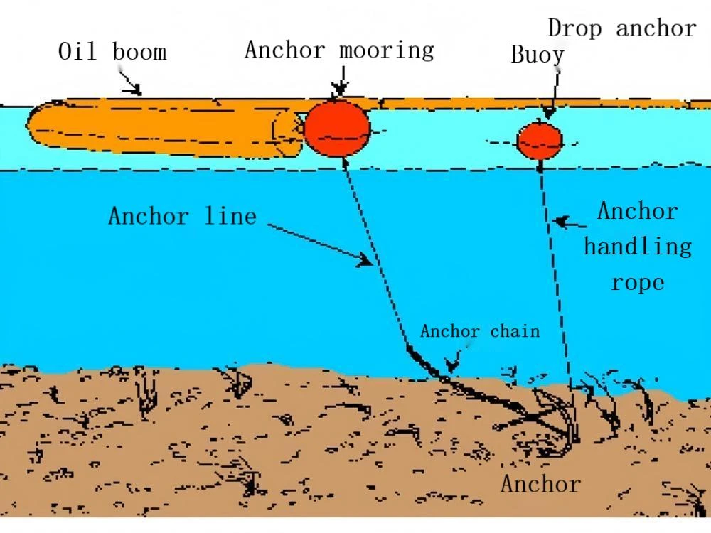
(3-21 Deployment forms of anchors used)
To prevent the anchor from being lifted by wave action, the length of the rope connecting the anchor and the anchor ball should be at least three times the water depth. The length of the anchor rope Under different sea conditions: In general sea conditions, the length of the anchor rope is five times the water depth; in calm waters, the length of the anchor rope is three times the water depth; under adverse sea conditions, the length of the anchor rope is seven times the water depth.
The size of the anchor ball is determined by the weight of the anchor. Usually, the volume of the anchor ball is 60 to 250 liters. From a safety perspective, to prevent the anchor from being retrieved for too long and affecting the rapid movement of the oil containment boom, a quick-release device, such as a snap ring, is usually used between the anchor ball and the oil containment boom.
During the use of the anchor, there may be situations where the anchor rope breaks or gets stuck. To facilitate the retrieval of the anchor, the position of the anchor is usually marked by a throwing anchor float; when the anchor gets stuck, the anchor can be retrieved from the opposite direction by using the throwing anchor float and the pulling anchor rope. The length of the rope between the anchor and the throwing anchor float should be at least twice the water depth.
6.4 Ankrajlar kullanılırken dikkat edilmesi gereken hususlar
In the practice of oil spill emergency response, after continuous exploration and research, some guidelines have been summarized and are worthy of reference. First, when deploying oil booms in waters with high flow velocity, it is advisable to drop the anchor first, then deploy the oil booms, and finally fix the oil booms at an appropriate position. In waters affected by tides, flow velocity, and waves, when deploying oil booms, the ropes for fixing the oil booms should have sufficient slack. Besides using anchors to fix the oil booms, objects such as trees on embankments and pillars of bridges can also temporarily fix the oil booms. In some waters (such as rivers), based on the fixed flow direction, an appropriate oil boom can be selected and one end can be fixed for a long time, allowing the other end to move freely. When necessary, the free-moving end can be used to gather the oil-spilling vessels.
Bölüm 3: Petrol Muhafaza Botlarının Arızalanması ve Önleyici Tedbirler
The failure of the oil containment boom refers to the phenomenon where the spilled oil that is contained by the oil containment boom escapes from above or below the boom, thereby reducing the effectiveness of the boom. After the oil containment boom is deployed, due to various environmental factors and deployment techniques, various failure phenomena may occur. This section mainly introduces the causes and preventive and corrective measures for failure phenomena such as oil spill carrying escape, oil spill leakage, oil spill splashing, boom overturning, boom sinking, and boom structural damage.
1. Sürüklenme Arızası
The phenomenon of oil escape from containment is that oil droplets constantly detach from the bottom of the oil film under the action of water flow and re-aggregate to form a new oil film on the other side of the containment barrier, as shown in Figure 3-22. This phenomenon is caused by factors such as flow and waves. When the flow and waves are in the same direction, relative to the fixed containment barrier, the movement speed of the spilled oil is the sum of the speed of waves and flow. When this speed exceeds 0.7 knots (0.36 m/s), turbulent flow will occur below the bottom of the contained oil film, causing oil droplets to detach and escape with the turbulent flow. Some of the escaped oil droplets will re-emerge on the other side of the containment barrier and form a new oil film.
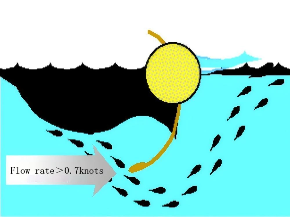
(3-22 Entrainment Failure)
In actual containment operations, the phenomenon of oil spill carrying away is inevitable. To minimize the occurrence of oil spill carrying away, the vertical flow velocity of the oil spill towards the containment boom should be reduced. Therefore, when towing containment booms in open waters, this goal can be achieved by lowering the towing speed (relative to the flow velocity); when deploying relatively fixed containment booms and other containment devices in rivers, the only solution is to form a certain angle between the deployment of the containment boom and the flow direction, thereby reducing the vertical flow velocity relative to the containment boom and guiding the floating oil to the area with relatively lower flow velocity to alleviate the carrying away of the oil spill.
2. Drenaj Arızası
Drainage Failure It refers to the phenomenon where the oil spill from the containment system spontaneously escapes from the bottom of the containment baffle skirt. As shown in Figure 3-23. The main reasons for this phenomenon are two:
1. If the amount of spilled oil enclosed within the inner side of the oil containment boom is too large, exceeding the capacity of the boom skirt to control the spillage, the spilled oil will escape from beneath the skirt. Usually, compared with the escape of spilled oil carried away by the wind, the amount of oil escaping from the leak is larger. To prevent the enclosed spilled oil from leaking, first of all, it is necessary to promptly recover the enclosed spilled oil using skimmers or other oil collection devices, or deploy oil-absorbing containment booms in the direction of the reverse flow. Secondly, the speed of the boom’s dragging relative to the oil film can be reduced to avoid concentrating too much spilled oil and failing to recover it in time.
2. The shape of the skirt of the oil containment boom has deviated abnormally. The ideal shape of the skirt should always slightly curve towards the direction of containing the spilled oil, forming a slightly curved arc. Otherwise, it is very likely to cause the leakage of the spilled oil contained by the boom. Sometimes, due to excessive water pressure, the skirt may flip backward, resulting in the spilled oil contained by the boom escaping from beneath the oil containment boom. To address this problem, some have attempted to increase the height of the skirt to solve the issue. However, experience shows that increasing the depth of the skirt can only make the problem more severe. This is because the oil containment boom cannot block the flow of water but can only guide the water to flow away from beneath the skirt. The larger the skirt, the greater the water flow speed beneath it, and thus the oil is carried away from beneath the skirt. Practice has shown that the depth of the skirt should not exceed one-third of the water depth.

(2-23 Drainage Failure)
(2-24 Splash-over Failure)
Splash effect failure It refers to the phenomenon where the spilled oil from the containment boom overflows beyond the top of the dry deck of the containment boom, as shown in Figure 3-24. The failure of splash containment usually occurs in two situations. One is caused by the water environment. When the water area where the containment boom is controlling the spilled oil has breaking waves, that is, when the ratio of wave length to wave height is less than 5:1, the containment boom will experience splash containment failure. This situation is more likely to occur in shallow water areas. The main reason for splash containment failure is that the intervals between breaking waves are short, and the containment boom has difficulty keeping up with the rhythm of the waves.
Another situation where splash failure occurs is due to the structure of the oil boom itself. Improper structure can also lead to the occurrence of splash failure. For instance, the lower the freeboard, the more prone to splash failure. Oil booms with a low floatation-to-weight ratio (below 4:1) have poor wave resistance and will experience splash failure along with leakage failure when the wave height is high and the waves are large. To prevent splash failure, a wave-breaking oil boom that can absorb waves should be set upstream of the deployed oil boom. Additionally, when the wave height is 1.0-1.5m, high floatation-to-weight ratio oil booms should be used. This requires on-site commanders to be familiar with the local water conditions, understand the possible wave heights and wave shapes in the actual deployment environment, and select appropriate oil booms based on the water conditions in a timely and accurate manner.
(3-25 Planning Failure)
(3-26 Submergence Failure)
4. Planlama Başarısızlığı
Planning Failure It’s refers to the phenomenon of oil spill escape caused by the parallel force acting on the oil containment boom, resulting in the boom tilting parallel to the water surface, as shown in Figure 3-25. This situation mainly occurs because the direction of the strong wind and the rapid current on the water surface is completely opposite, meaning that the directions of these two forces acting on the oil containment boom are exactly opposite, causing the boom to tilt. This phenomenon is prone to occur when the contact area of the oil containment boom with the water surface is too small. Therefore, when selecting the oil containment boom, this point should be fully considered. Barricade-type and curtain-type oil containment booms may also experience this tilting phenomenon.
To prevent the failure of the floating platform from tipping over, it is advisable to consider adding sufficient counterweights on top of the oil containment boom or adopt the method of shortening the counterweight chain of the oil containment boom to keep the oil containment boom in a normal state as much as possible and avoid the occurrence of the tipping phenomenon. In addition, using oil containment booms with a larger contact area with water, such as cylindrical floating bodies, can also greatly reduce the occurrence of such a phenomenon.
5. Su Altında Kalma Arızası
Submergence Failure It refers to the phenomenon where oil spill escapes due to the fact that the oil booms are pressed below the water surface by external forces under high-speed towing, as shown in Figure 3-26. This phenomenon occurs when the towing speed is too fast, and it usually happens before the actual oil containment control is carried out during the process of towing the oil booms to the appropriate position. Another situation is that, if the oil booms have already controlled some oil, leakage failure will occur simultaneously with immersion failure. The solution and prevention method for immersion failure is to reduce the towing speed of the oil booms or to use oil booms with a float-to-weight ratio greater than 10:1. Generally speaking, curtain-type oil booms with a float-to-weight ratio greater than 10:1 can be towed at a speed of 3 knots without experiencing immersion failure.
6. Yapı Arızası ve Muhafaza Bomuna Etki Eden Kuvvetlerin Hesaplanması
Structure Failure and Calculation of the Forces Acting on the Containment BoomIt refers to the situation where the force exerted on the oil containment boom exceeds the breaking strength of the materials used, resulting in the damage of the oil containment boom. The forces acting on the oil containment boom are usually composed of the pressure from water and wind, friction, and the vector sum of the shape of the oil containment boom and the wind, current, and wave velocities.
The main reasons for the structural damage of the oil containment boom are: the speed of towing the oil containment boom is too fast (the speed of the oil containment boom is relative to the water surface); the oil containment boom gets caught by protruding or sharp obstacles; the oil containment boom gets tangled by the propellers of the towing vessel; the oil containment boom is too long, resulting in increased friction, etc.
In order to avoid damage to the oil containment boom, during the deployment and towing of the oil containment boom, the following points should be noted: Personnel conducting oil spill containment operations should have received technical training and be familiar with and understand the on-site operation environment; During the operation, strictly follow relevant procedures; Communication should be kept unobstructed, and pay attention to observing whether there are phenomena such as the boom being carried away, the boom sinking, or the formation of strong turbulence at the tail of the boom, etc., and take timely measures (such as reducing the towing speed or adjusting the direction of movement) based on these phenomena that occur.
Bölüm 4: Petrol Taşkın Bariyerlerinin Geri Kazanımı ve Depolanması
The deployment of oil booms can be divided into two types: long-term deployment and temporary deployment. Long-term deployment does not have the problem of frequent recovery. Generally speaking, it is the temporary deployment of oil booms that involves recovery, cleaning, maintenance and storage. This section introduces the operation steps and precautions for the recovery, cleaning, maintenance and storage of oil booms.
1. Petrolle Mücadele Bomlarının Kurtarma Operasyonu
The recovery operation of oil-fighting booms is the reverse operation of deployment. The recovery operation of solid float type oil-fighting booms is relatively simple but the recovery speed is slow; while the recovery operation of inflatable oil-fighting booms is relatively easy. The main steps of the recovery operation are as follows:
1. The auxiliary tugboat should first release the towing cables of the oil containment boom to make it operate in a state where it is only connected and towed by the main tugboat.
2. According to the water conditions, it is best for the main tugboat to sail against the current to allow the oil containment boom to unfold in a straight line behind the stern of the vessel.
3. Use the winch or the boom for winding the boom to slowly tow the boom onto the deck or wind it onto the boom reel.
4. During the recovery process of the inflatable oil containment boom, it is necessary to release the gas in the gas chambers while recovering and keep the gas chamber covers well preserved.
5. During the winding process, check whether the oil containment boom is damaged and make records.
2. İyileşme süreci sırasında alınacak önlemler
1. During the recovery of the oil-absorbing boom, safety should be ensured. The oil-absorbing boom that has been smeared with oil will be very slippery, which increases the difficulty of the recovery operation and may also dirty the equipment and operators. The deck will also become slippery due to the oil.
2. One person should be assigned to conduct on-site inspections of the recovered oil-absorbing boom and make records. Damaged ones should be repaired.
3. Appropriate amounts of oil-absorbing felt should be available on the deck to wipe off the spilled oil on the deck in time.
4. If the recovered oil causes the deck to become extremely slippery and poses a safety hazard, the operation can be suspended. After appropriate cleaning, the operation can be resumed.
3. Petrol Muhafaza Botlarının Temizlenmesi
For oil containment boats that are repeatedly used in oil spill containment operations, they generally do not require cleaning. However, if the oil containment boats are used to protect non-oil-spill areas or for shoreline oil spill removal operations and are left idle or stored in the warehouse during the process, cleaning is necessary.
When cleaning the oil containment boats, they should be cleaned using a dedicated cleaning device while being recovered. If there is no dedicated cleaning device, the oil containment boats can be recovered first and then cleaned onshore. However, a cleaning area should be set up to avoid the spread of the cleaned wastewater, which could cause secondary pollution.
Manual cleaning of the oil barrier net should start with gently scraping off the thick oil layer adhering to the surface of the net with a scraper (preferably made of wood). Then, it should be cleaned with warm water or scrubbed with a detergent brush. Finally, it should be wiped clean with an oil-absorbing cloth. Under good weather conditions, 6 to 12 workers can clean the oil barrier net for 305m in one day.
When using the oil barrier net cleaning device, the angle between the spray gun and the surface of the oil barrier net for cleaning should be less than 45°. The water temperature used should not be too high. The lower the temperature is, the better, as long as it can remove the surface oil. Avoiding premature aging of the protective coating of the oil barrier net.
The oil barrier net should be rinsed clean with fresh water, placed in a cool place to dry, and then stored in the warehouse.
4. Petrolle Mücadele Bomlarının Depolanması ve Bakımı
The storage and maintenance of oil-fighting booms are directly related to whether a rapid oil spill emergency response can be carried out and whether effective containment operations can be implemented. To ensure a rapid response, the storage locations of oil-fighting booms should be as close as possible to the wharf, the operation site, and the sensitive resource protection areas, and the storage locations should be convenient for the entry and exit of vehicles and ships. For oil-fighting booms stored outdoors, it is necessary to ensure that the drainage conditions of the storage locations are good and to pay attention to pest control, moisture prevention, and avoiding direct sunlight exposure. For those stored indoors, it is also necessary to pay attention to moisture prevention and ensure good ventilation conditions. Depending on the situation, necessary measures should be taken in advance to prevent pests and avoid damage to the booms (such as spreading rat poison, etc.). For oil-fighting booms that need to be folded for storage, they should be placed on shelves and no other items should be stacked on top to avoid excessive pressure causing deformation of the booms. Regularly unfold the folded oil-fighting booms for inspection and re-fold them when necessary, avoiding the original folding marks. If the oil-fighting booms need to be stored on reels, it is necessary to avoid twisting during the winding process and regularly unwind all the oil-fighting booms that are wound to check and then re-collect them. The maintenance of oil-fighting booms mainly refers to daily maintenance and maintenance after the completion of the recovery operation. After the completion of the recovery operation, the maintenance mainly checks whether the booms are damaged, whether the accessories are complete or whether they need to be replaced and repaired; daily maintenance generally checks whether there are damages, cracks, fiber aging, corrosion or damage to the connectors caused by pulling and other loading and unloading reasons of the oil-fighting booms, and performs necessary repairs and replacements; for oil-fighting booms that are long-term placed in water areas, regular maintenance should also be carried out. Generally, according to specific circumstances, the oil-fighting booms should be towed ashore regularly to remove marine organisms and other adhering substances attached to the surface of the booms; regardless of which maintenance and maintenance are carried out, detailed records should be made and inspection and maintenance items should be arranged based on the records to ensure that all contents related to the oil-fighting booms can be comprehensively inspected and maintained within a certain period of time, so that the oil-fighting booms are always in a good standby state.