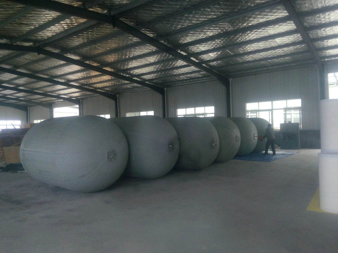
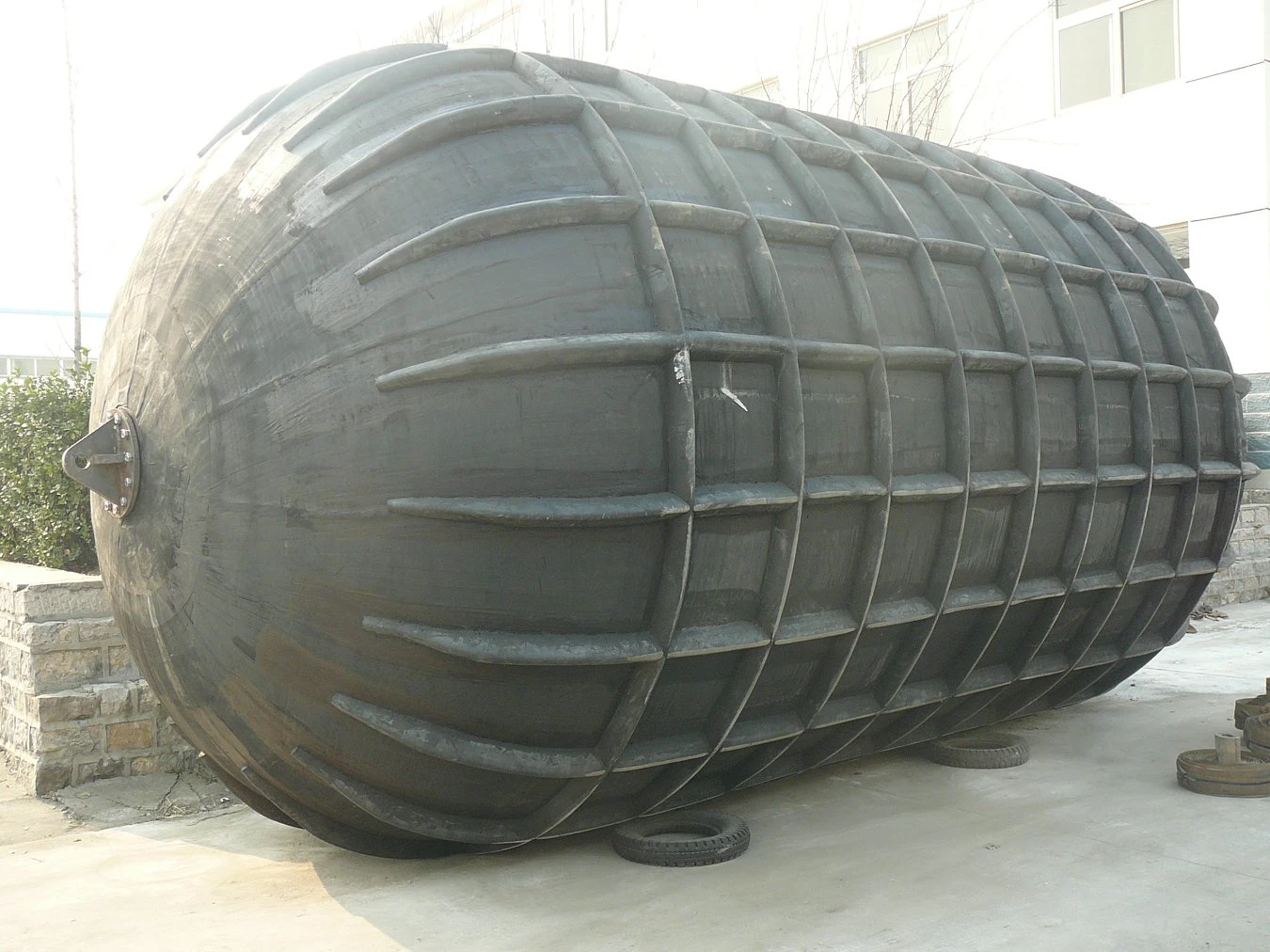
Que sont les défenses pneumatiques à élingue ?

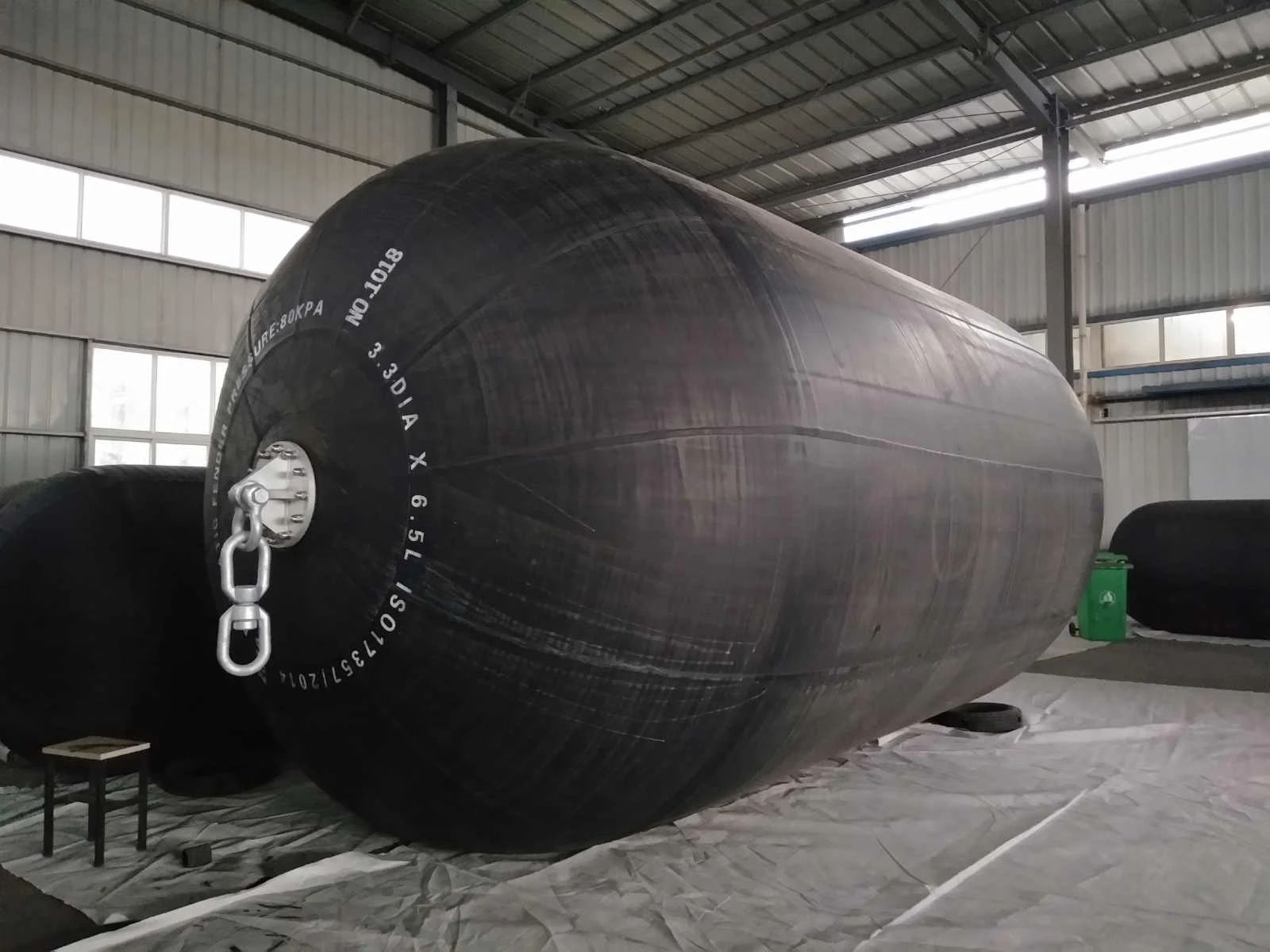
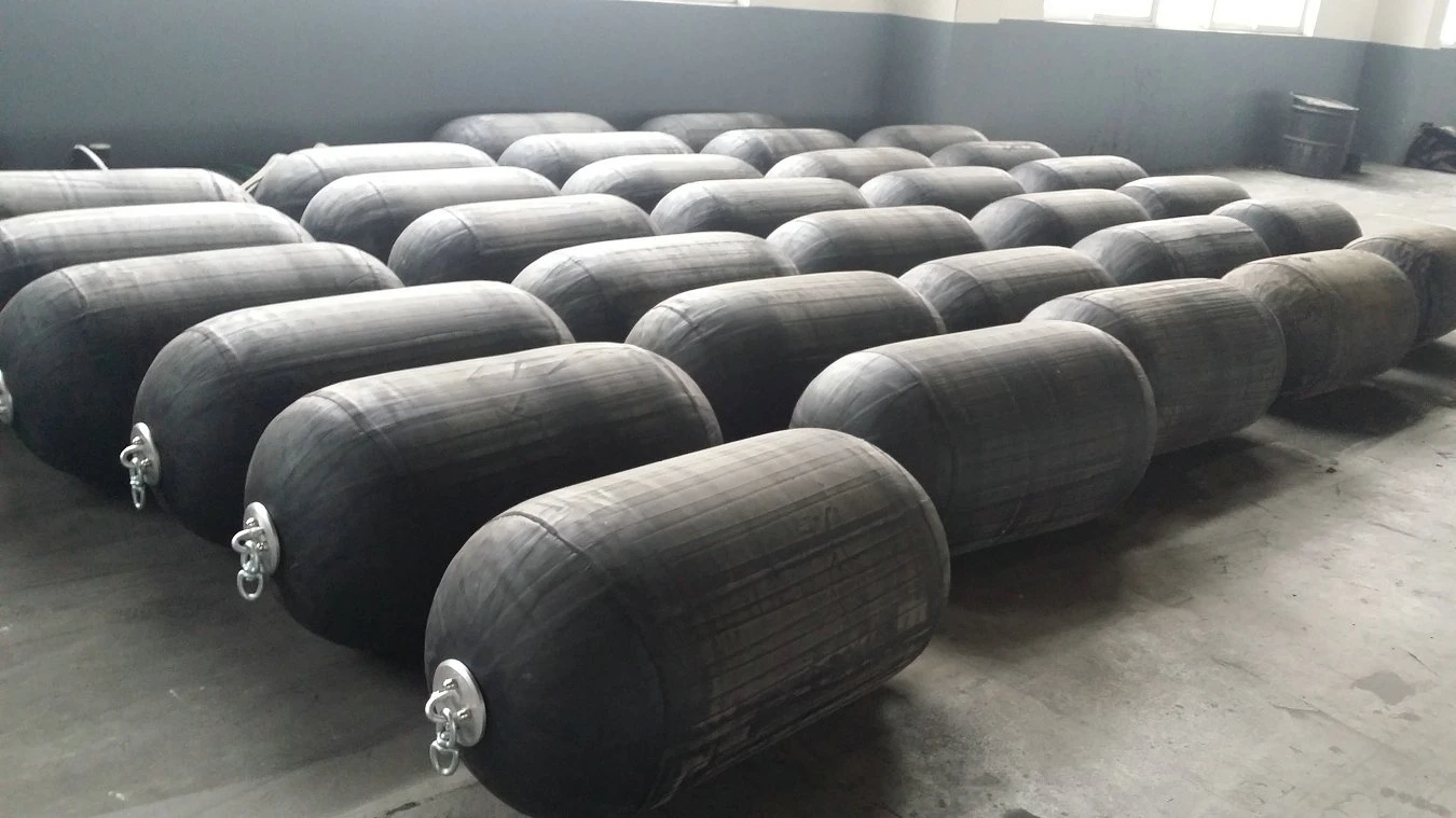
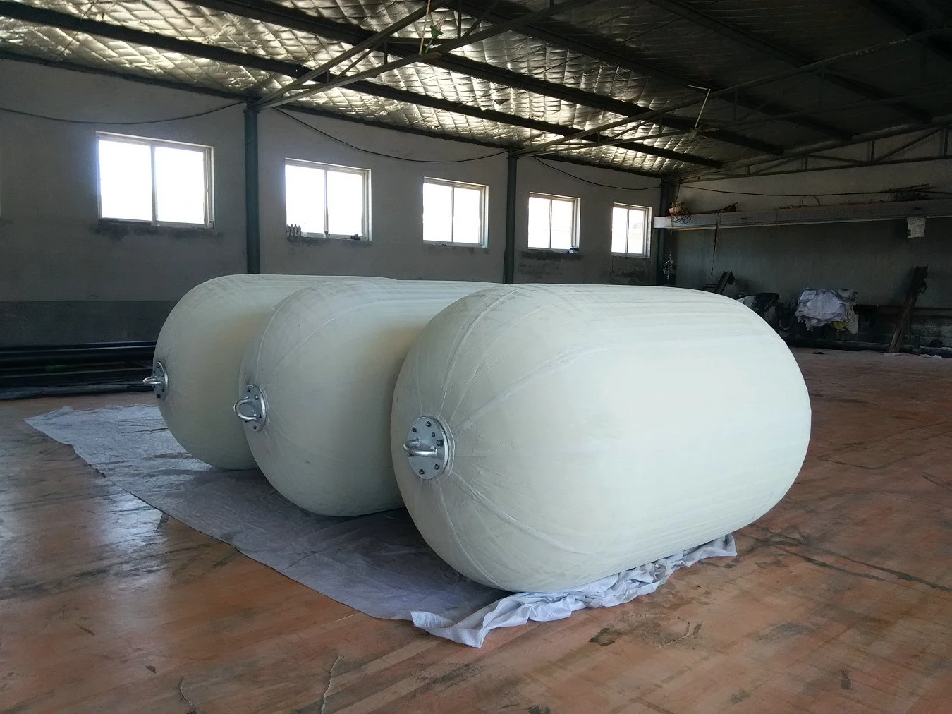
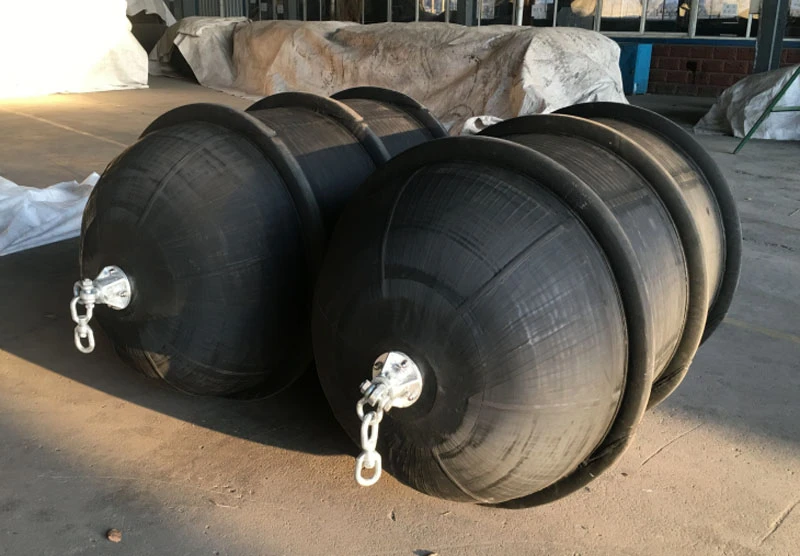
Le garde-boue pneumatique à élingue est semblable au garde-boue Yokohama, mais il n'a pas de filet extérieur. Il se compose de trois couches : une couche de caoutchouc extérieur, une couche de corde synthétique et une couche de caoutchouc intérieur. Cette aile est dotée d'un caoutchouc résistant à l'extérieur. Cette couche de caoutchouc améliore la résistance aux dommages opérationnels. Chaque extrémité de l'aile est équipée d'une bride, d'une manille et d'un émerillon, ce qui permet d'y attacher une chaîne ou un câble. Ces ailes Yokohama pour élingues sont conçues pour être gonflées et dégonflées à plusieurs reprises. Cette conception les rend faciles à utiliser, à transporter et à stocker.

Obtenir un devis

Caractéristiques du harnais

Paramètres techniques de l'étrier pneumatique

Tableau 1 - Exigences en matière de dimensions et de performances des défenses pneumatiques 50
Taille nominale diam_x001f_eter x longueur mm Pression interne initiale kPa Absorption d'énergie garantie (GEA) Force de réaction à la déflexion du GEA (R) Pression dans la coque (pression interne) à la déflexion du GEA (P)
Valeur minimale à la déflexion 60 ± 5 % kJ Tolérance ±10 % kN Valeur de référence kPa
500 x 1000 50 6 64 132
600 x 1000 50 8 74 126
700 x 1500 50 17 137 135
1000 x 1500 50 32 182 122
1000 x 2000 50 45 257 132
1200 x 2000 50 63 297 126
1350 x 2500 50 102 427 130
1500 x 3000 50 153 579 132
1700 x 3000 50 191 639 128
2000 x 3500 50 308 875 128
2500 x 4000 50 663 1 381 137
2500 x 5500 50 943 2 019 148
3300 x 4500 50 1 175 1 884 130
3300 x 6500 50 1814 3015 146
3300 x 10600 50 3067 5257 158
4500 x 9000 50 4752 5747 146
4500 x 12000 50 6473 7984 154
Tableau 2 - Exigences en matière de dimensions et de performances des défenses pneumatiques 80
Taille nominale diamètre × longueur mm Pression interne initiale kPa Absorption d'énergie garantie (GEA) Force de réaction à la déflexion du GEA (R) Pression dans la coque (pression interne) à la déflexion du GEA (P)
Pression dans la coque (pression interne) à la déflexion du GEA (P) Tolérance ±10 % kN Valeur de référence kPa
500 x 1 000 80 8 85 174
600 x 1 000 80 11 98 166
700 x 1500 80 24 180 177
1 000 x 2 000 80 63 338 174
1200 x 2000 80 88 390 166
1 350 x 2500 80 142 561 170
1 500 x 3000 80 214 761 174
1 700 x 3000 80 267 840 168
2000 x 3500 80 430 1150 168
2 500 x4 000 80 925 1815 180
2 500 x 5 500 80 1317 2653 195
3300 x4500 80 1640 2476 171
3300 x 6500 80 2532 3961 191
3 300 x 10 600 80 4281 6907 208
4 500 x9 000 6633 80 7551 192
4 500 x 12 000 80 9037 10490 202

Obtenir un devis

FAQ

A sling type fender is a type of fender suspended by slings, wire ropes, or chains. The fender itself is not rigidly fixed to the dock structure but is suspended from the ship’s side or the quay wall to absorb the impact force during berthing. This structure is relatively simple and offers flexibility in installation and adjustment.

Jerryborg Marine offers a variety of sling type fenders and matches appropriate lifting methods to the fender dimensions. When configuring fenders, we consider the fender’s own weight and actual stress conditions to avoid focusing solely on the fender itself while neglecting the suspension system.

Sling type fenders are commonly used for temporary berthing, berthing of work vessels, or dock locations where installing fixed fenders is inconvenient. In these scenarios, the fender needs frequent adjustments to its height or position, and a suspended structure is easier to operate.

The forces on a sling-type fender come not only from hull impacts but also from the slings and wire ropes. Therefore, the lifting method must have sufficient load-bearing capacity and maintain a relatively even stress distribution.

When providing sling-type fenders, Jerryborg Marine considers the lifting point locations and accessory selection simultaneously. If necessary, they will also advise customers to adjust the lifting method to avoid fender tilting or excessive localized stress during use.

External accessories are crucial for the safe use of a sling-type fender. Wear or improper selection of slings, wire ropes, and connectors will directly affect the fender’s stability.

Jerryborg Marine checks the compatibility of the fender body and accessories before shipment. For projects with high-intensity use, we also remind customers to pay special attention to these vulnerable parts and plan for inspection and replacement in advance.

During use, it is necessary to regularly check the fender surface for abnormal wear and observe the condition of the suspension parts. If the fender is kept at the same height for a long time, attention should also be paid to whether there is localized stress concentration.

At the time of project delivery, Jerryborg Marine usually provides basic usage suggestions based on the actual usage method to help customers reduce unnecessary wear and tear and extend the service life of the fender.

When selecting a sling type fender, it is not enough to just look at the diameter or length; it is also necessary to consider the berthing vessel type, berthing method, and frequency of use. Different projects have different requirements for fender reaction speed and cushioning capacity.

During the actual selection phase, Jerryborg Marine will assist in confirming the fender size and configuration based on the customer-provided project background. If there’s anything you’re unsure about, feel free to communicate directly instead of applying generic parameters on your own.

Cas de projets